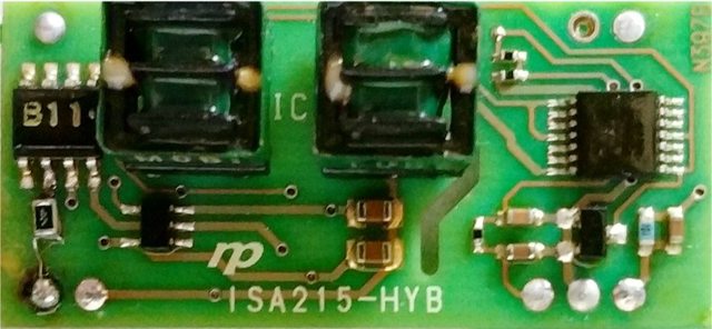
that tells me that the op amp is okay and doing its job. You are getting the same 0.15 voltage difference that Gencis found in his testing.
All measurements are between one via or pin and ground.
if you can put a scope on the output pin 3, see what it looks like, then move it up the board to the junction above the tiny resistor of the output low pass filter, and compare how it looks? Maybe the LPF is leaking and pulling the output voltage low?
That little resistor measures 275 Ohms on my board. i'm hoping that one of those capacitors of the low pass filter is leaking signal to ground and causing this fault. [That would be the easiest to fix].
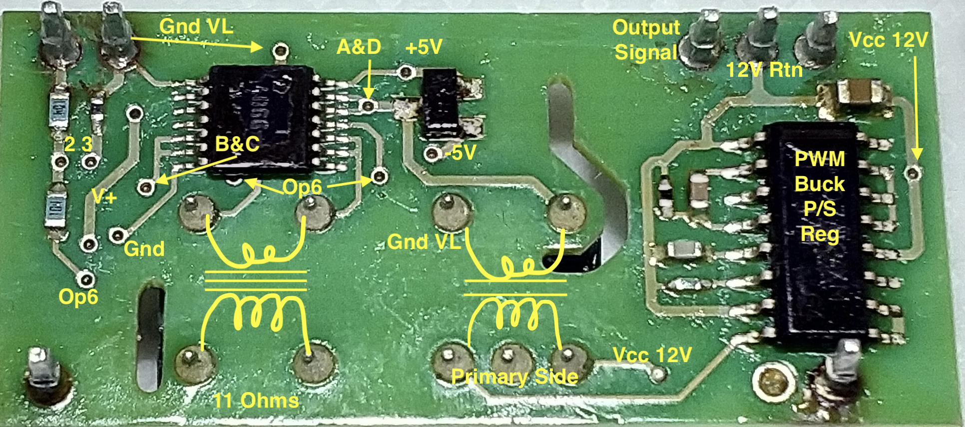
That ic on the right is a 4066 switch. Pin 1 is the bottom pin on the right side.
The control gates are held up by the voltage divider of the leftmost upper via.
The input signals from the other transformer come into pins 1&4 for the first half of the oscillation, and pins 8&11 for the second half of the oscillation. Could you look at those on a scope to compare that they have the same looking waveform, and what is the frequency?
The gated output appears on pin 2&3 for the first half and pins 9&10 for the second half. These get routed to the LPF and on to the output pin 3.
The output of the OpAmp gets switched by the 4066 on the bottom side thru the transformer on the left; the output of that transformer gets sent to the 4066 on the top side.
Here is the bottom layer of the hybrid for reference


