civjdh
Member
Thanks Kiev, I'll head over there and see what they say. Will pop back in with (hopefully) a resolution.

I'm flattered.kiev said:Simon (username: DBMandrake) is the smartest guy in Scotland for solving problems and he knows how to open a pack and change cells because he did it. There is an EV forum at SpeakEV with lots of UK and EU folks, that may be able to help you find somebody local.
Thanks.kiev said:i hope the Laef works out well for you, they are nice cars--almost luxury compared to the triples. i fixed one up for my daughter and she is loving it.
Take care, let's hope we can all survive this virus and lockdown mess.
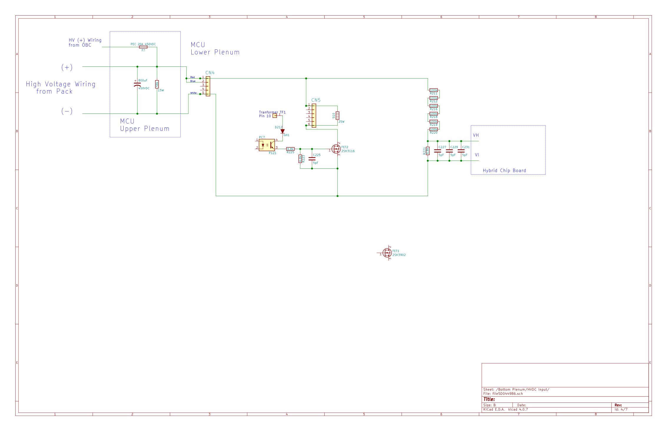
kiev said:Yes it does go to the bottom of the lower right corner of Lic's photo, to Connector CN4, labelled "VDC". The red and blue wires are from the (+) side of the pack and route to pins 1 and 2; the white wire is from the (-) side of the pack and routes to pin 5.
CN4p1 then routes to CN5p1, labelled "VDC-R", which is a red wire running to the large silver-colored resistor on the heatsink, ~50W power resistor, 510 Ohms. The other end runs back to CN5p5, thru a white wire. This is the quick bleed resistor for the large "condenser", the big black 800 uF capacitor in the top plenum. CN5p5 routes to the Drain of the big FET2; the gate is driven by the output of optocoupler PC7; and the Source is connected to pack (-) thru CN4p5. This RC combination has a time constant of about 0.4 seconds and would drain the big cap in about 1.2 seconds.
In parallel from CN4p1 is a voltage sensing circuit running from CN4p1 to a series string of six 100k resistors and a 6.8k that route to the hybrid chip board pin 1 labelled "VH" with the return on pin 2 labelled "VI", that connects back to pack (-) thru CN4p5. This is a voltage divider to drop the high voltage down by a factor of ~90: for 360 Volts at the condenser, the voltage at the Hybrid is about 4 Volts.
If any portion of that sense hybrid circuitry were not working properly, then it may be that the HV is not reading properly.
Your test to remove the jumper wires at the pack buss bars seems to indicate a problem down below on the main board in the bottom plenum of the MCU. Did the car go to READY when you ran that test? i would guess not, but you did prove that the bottom circuit is pulling down the pack voltage at the "condensor" and throwing the P1A15 DTC.
[edit: corrected some hasty notes from yesterday and added details of voltage divider and fast bleed resistor; and sketch of circuit]
sketch of circuit


kiev said:Thank you for looking at this in detail, it's always good to have someone else to check the drawings.
My finding was from a measurement on the board using smart tweezers; with all the parallel paths it is not likely an accurate value.
i haven't removed any parts to measure separately, but for sure i would be happy to change the values to a better measurement. 3 parallel 390nF gives nearly 1uF, so that is likely the design target and the three were used to provide some redundancy?