ThisNonsense
New member
- Joined
- Dec 1, 2018
- Messages
- 4
A couple of months ago I started having an issue with a couple of cells in the pack of my Mitsubishi Minicab Miev. It's a van based off the iMiev, so much so that it's almost just a different shell around the outside. Initially it was just one cell that had gone bad, but I could see that it was self discharging slowly and the balancing circuits weren't able to fix it during a charge and since there aren't a whole lot of iMievs in Australia to begin with I had to improvise a little.
Band aid fixes and recommendations for pack removal
The first fix as a bunch of 18650 cells that were recovered from laptop batteries and had their capacities tested to try to match it to the other cells in the pack. I won't go into this fix too much other than to say it held up surprisingly well until the inevitable happened about a month or two later and the pack of 18650s eventually started dying too (who would have guessed that laptop batteries don't like being discharged at 1C with peaks up to 2.5C? :roll: ).
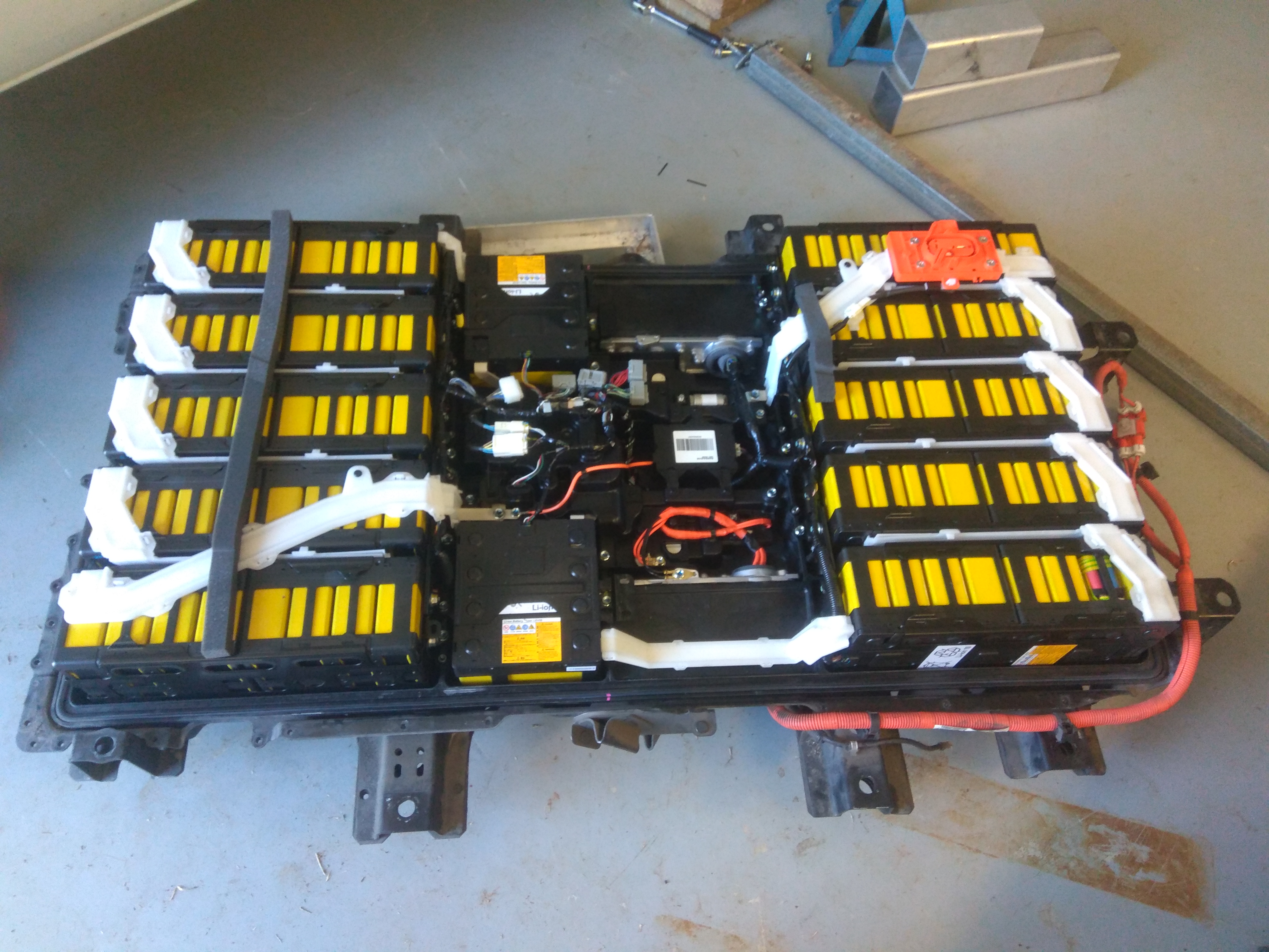
(Note the 18650 pack in the bottom right corner)
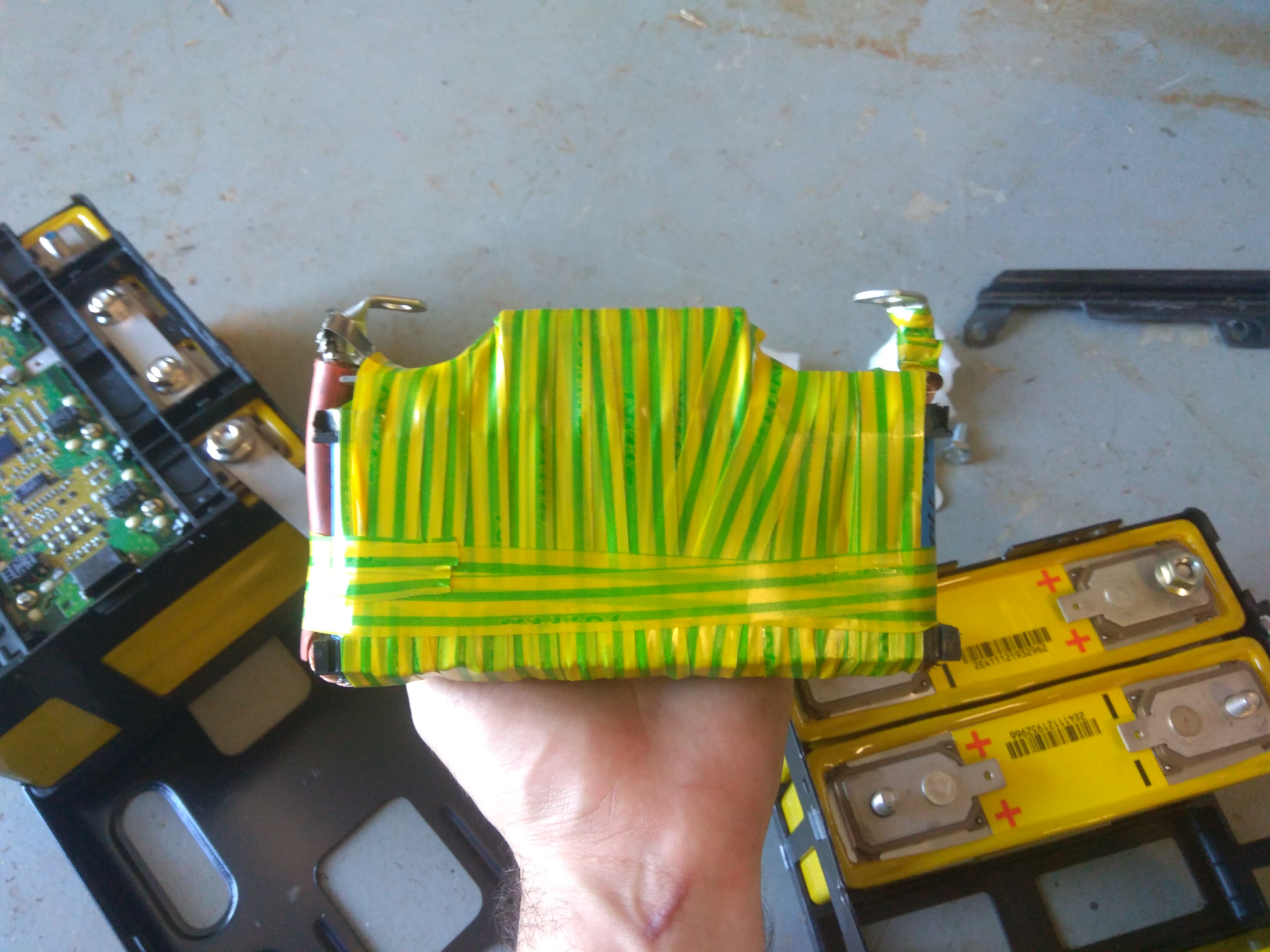
(Yes, it is held together with electrical tape and connected through welding cables. What else did you expect?)
Thankfully, by the time the 18650s were starting to become very unhappy another cell in the pack also started dying. So, now with two dying cells I decided to do the smart thing and grab some aftermarket 40Ah cells from Taobao (the rest of the LEV50 cells in my car are around 37Ah last time I was able to see full pack capacity). I also bought a 70Ah cell for my friend to use and to compare sizes against the LEV50s in my van.
Dropping the pack wasn't too hard since I'd done it before when I installed the 18650 pack, but I definitely recommend using a car hoist if you have access to one, but we made do with a couple of jacks, jack stands, some wooden blocks, and a pallet jack (though any kind of dolly can work). (If you're looking for a how to guide, check out https://www.speakev.com/threads/c-zero-battery-pack-repair.137750/) It would especially help to use a car hoist if things go wrong and you end up having to install, remove, and reinstall the pack several times because you either forgot to do things or things weren't connected properly!
Preperations for replacing the cells
It might not seem obvious if you've never stuck your head inside an iMiev battery pack, but there are a couple things you need to do before you can actually connect the new cell into the pack. Obviously there's the simply stuff like balancing, but there's also things like terminal connections and spacing, balancing connections, and cell packing. I'll try to deal with each one separately.
Firstly, the terminals on LEV50s have captive M8 bolts which connect to the bus bars between the cells. All of the batteries that I could find from China do not. So you'll need to make your own terminals. For this we used some 5/16" (I think?) brass threaded rod cut into short pieces, some annealed copper pipe which was crushed flat, and some brass nuts to suit the threaded rod. We crushed the pipe flat, tapped it for 5/16" thread, then screwed in short sections of threaded rod and soldered it in place. Then we soldered our home made bolts into place on the terminals of the batteries. The batteries we bought came with small tabs that I think ended up being zinc coated stainless steel. We removed the tabs beforehand because we didn't need them and wanted better contact between our bolt and the terminal.
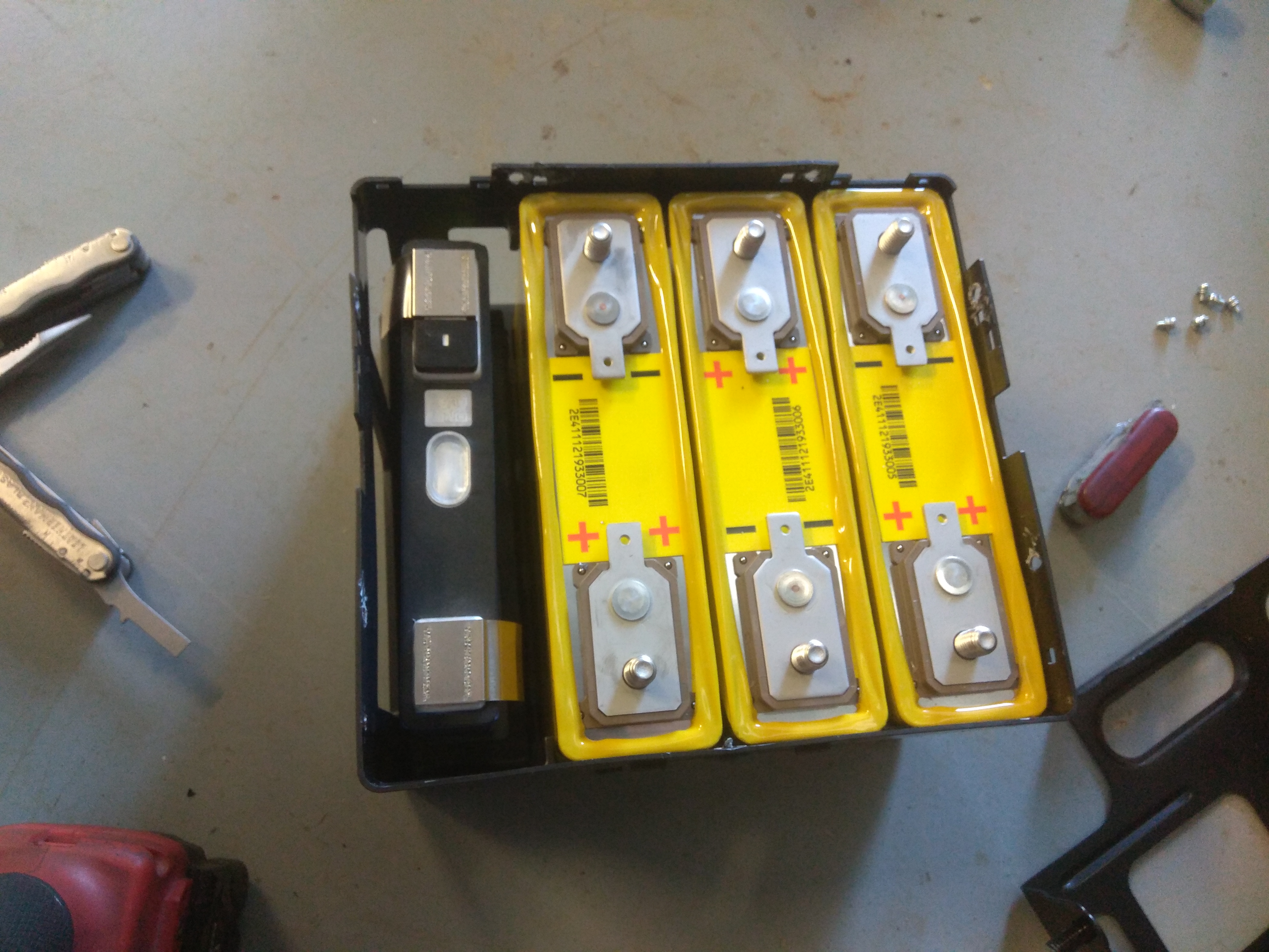
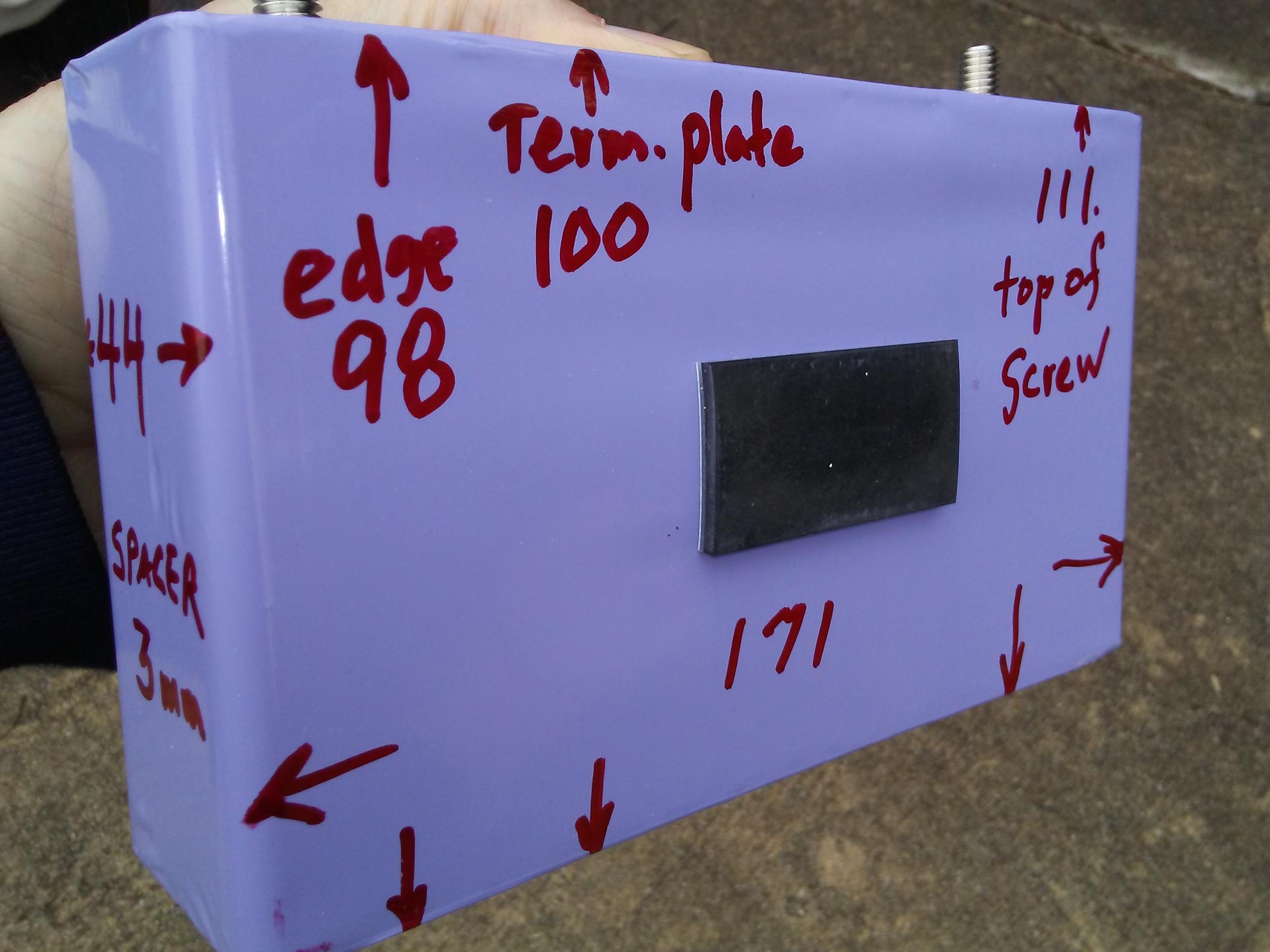
(The replacement cell is significantly smaller than the original cells. Possibly suggesting that it's not actually 40Ah after all. We also removed the tabs that you can see bent over the sides of the battery.)
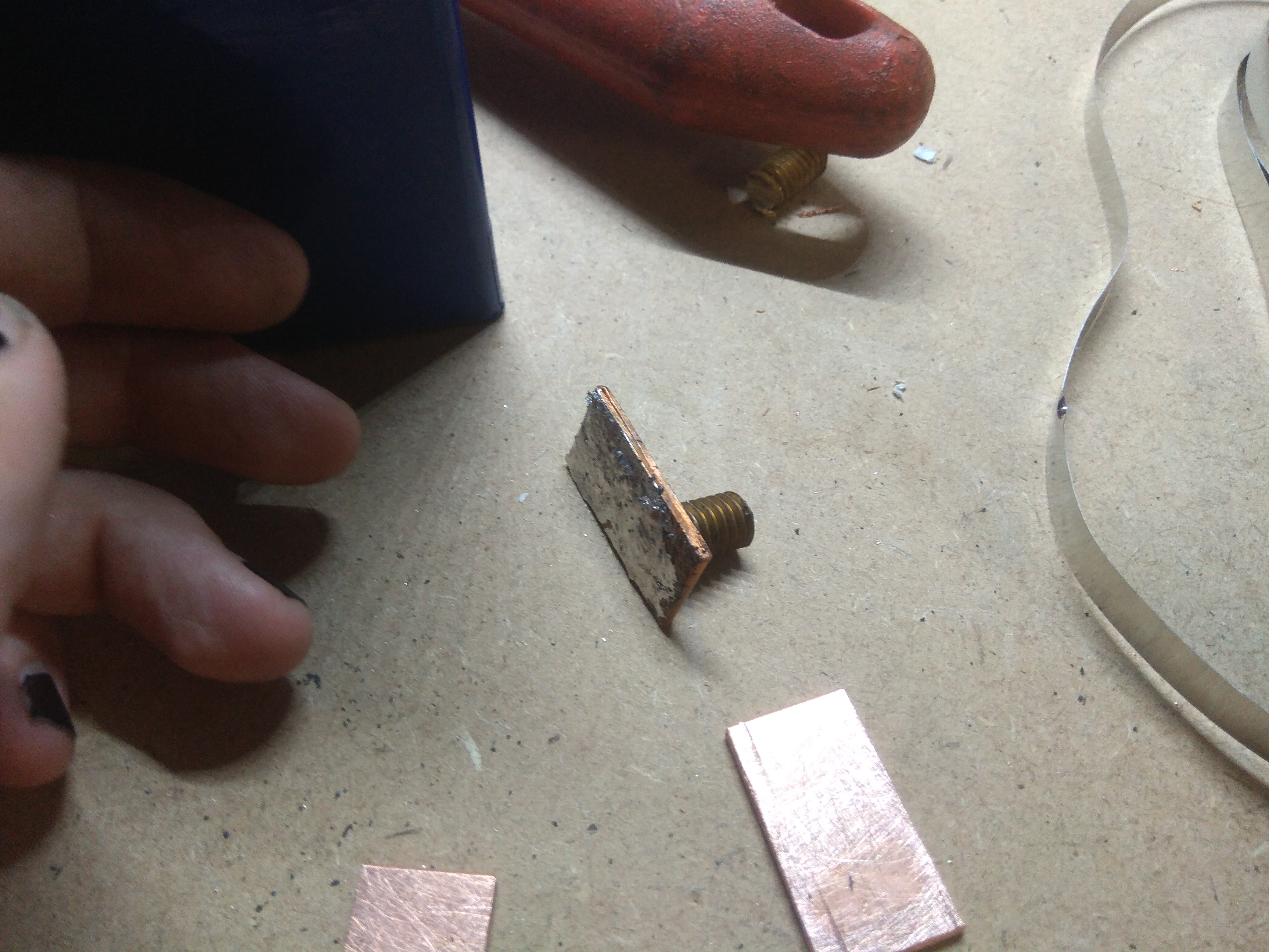
(Our little home made bolts. They were surprisingly easy to fabricate when you know a guy that used to run a sheet metal fabrication shop )
)
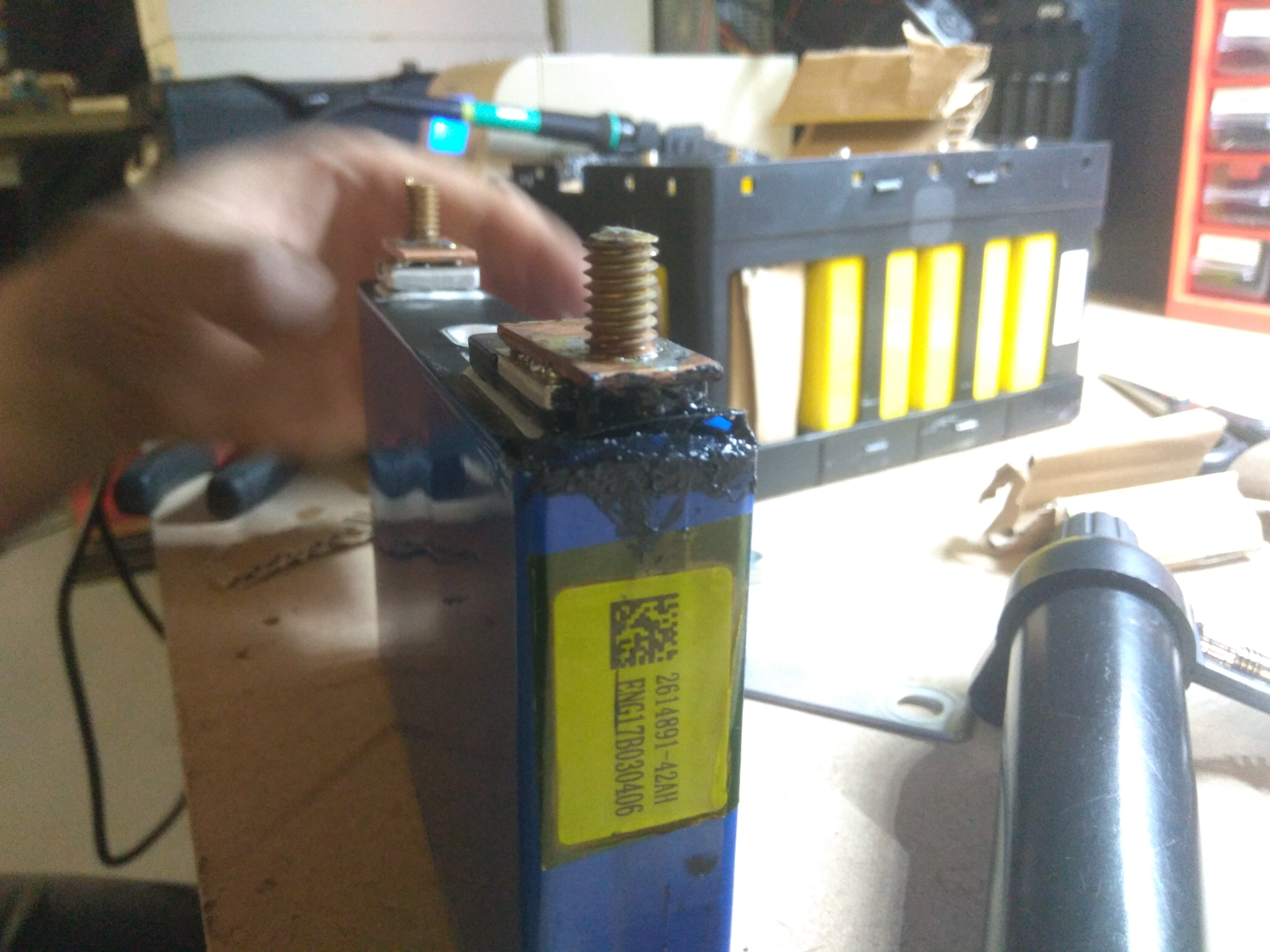
(Soldering took a bit of work, there's quite a bit of thermal mass to draw heat away from the bit you're trying to heat up. Don't mind the black goo, it is liquid electrical tape)
When it came to terminal spacing it worked out really well, the spacings of the terminals turned out to be close enough to the terminals on the LEV50s that we could just position the bolt in the right place on the terminal. If you need to extend the bolt past the end of the terminal I'd probably recommend using longer sections of the annealed copper tubing to get it in the right place.
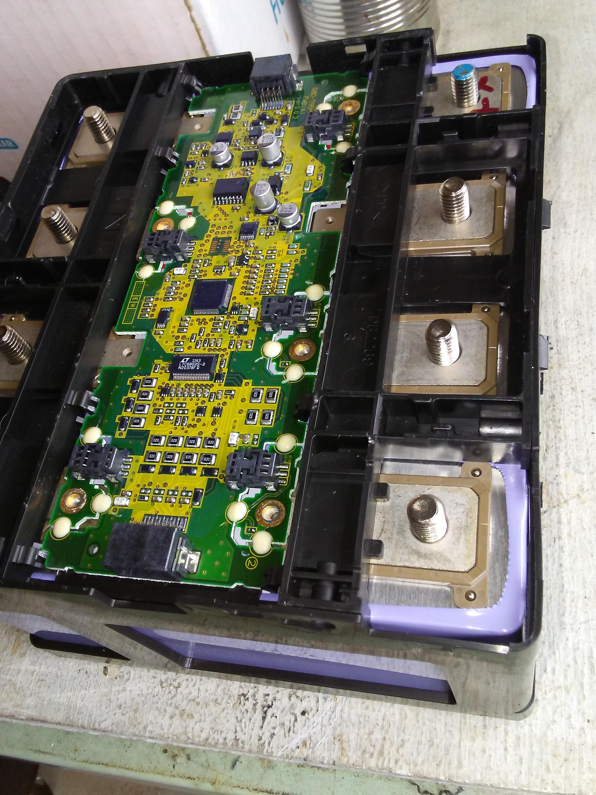
The next issue is the balancing leads. On the LEV50s in the iMiev, the balacing board screws directly on to one of the terminals of the cell itself with an M3 (I think?) screw. Unfortunately, the cells from China don't come with any tapped points on the terminal and we were unwilling to take the risk of trying to tap directly into the terminal. So what we did was take a small length of wire, solder one end to the the correct terminal, solder the other end to an M3 bolt then thread it through the hole in the balacing board and hold it in place with a nut. This seems to have worked successfully for the most part (more on this later). (No pictures of this section, it was done pretty late at night and we were done for the day)
Finally, packing. Since the new cells and the LEV50s are of a different size you'll need to make sure that the new cells can will be kept in place without putting any stress on the balance board or the tabs of the other batteries. For this project we ended up using spray foam insulation since it expands pretty well to fill the space and sets pretty hard to hold everything where it needs to be. Initially I was going to just use bits of corrugated cardboard, but ended up being talked out of it. I'm pretty happy with how it has held up so far. I've driven a little over 1000km since putting in the new cells (including some very harsh speed bumps in a school and a university) and everything has held up fine. The only thing I'd mention about using spray foam to hold stuff in place is that it makes and future service work pretty much impossible without having to ruin the foam.
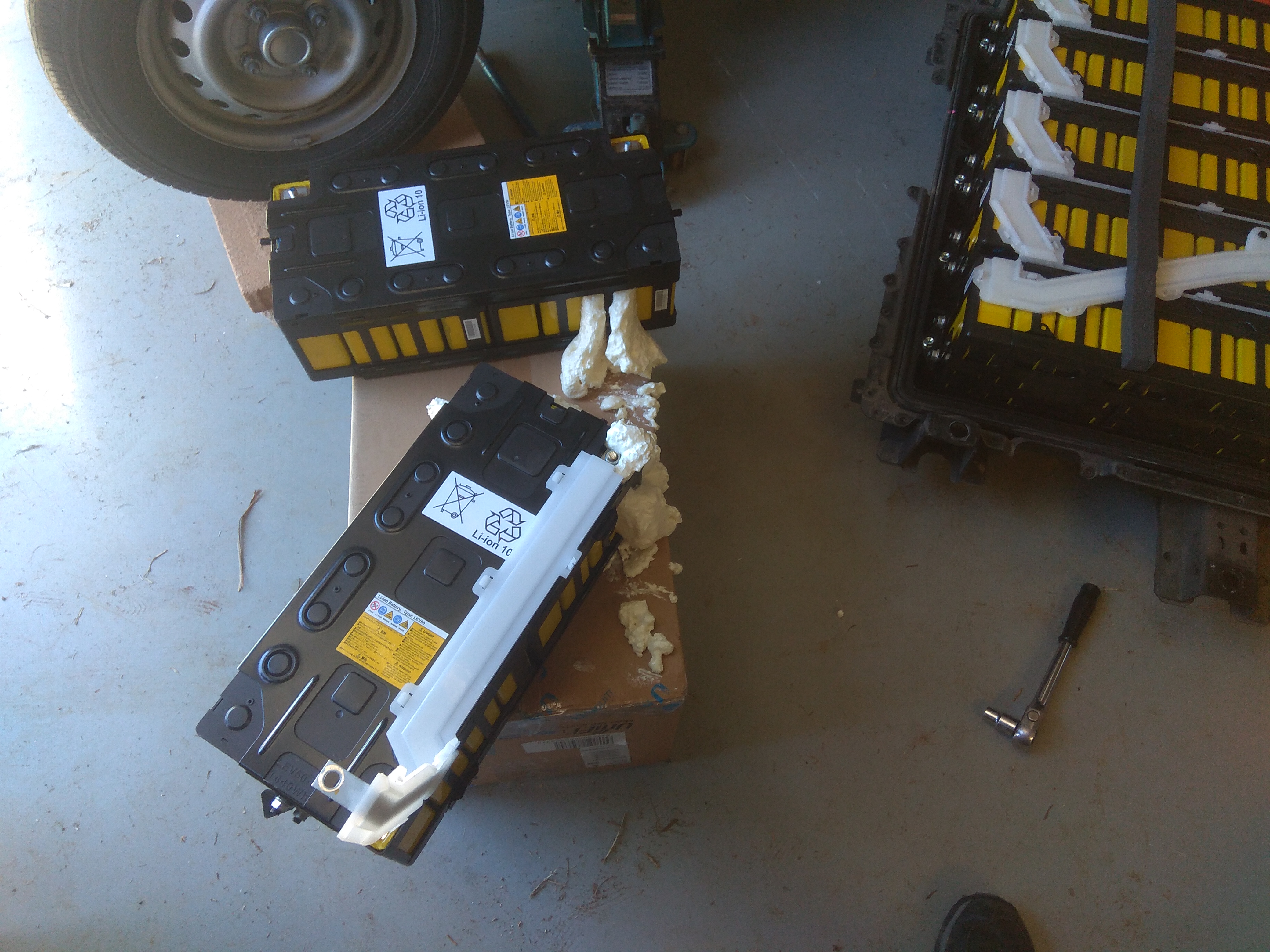
(There's quite a bit of spill over from the foam. We ended up cutting it away at one point in the hopes of speeding up the curing process. I think since there wasn't much surface area exposed to air it made it take a lot longer to set)
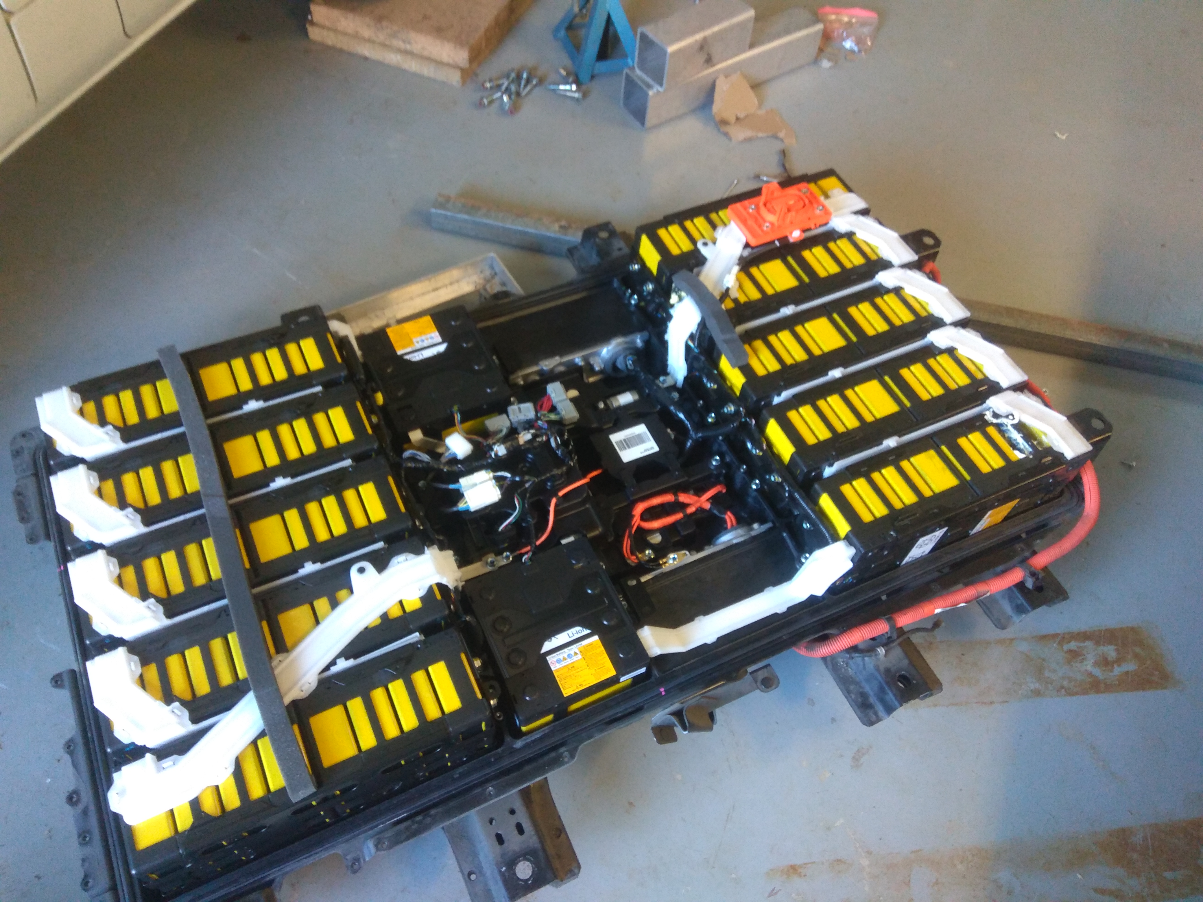
(You can see one of the replacement cells in the bottom right where the old 18650 pack was sitting. The other is covered by the disconnect busbar, it's right next to the length of foam.)
Issues encountered along the way
Everything seems to be going fine so far. There was a bit of a problem initially, mainly caused by me forgetting to install a couple of bolts when putting the battery back together which resulted in one of the cells disconnecting entirely and the van having to be towed back to a friends house and spending nearly three weeks in his shed. I think something to do with the jostling and sporadic connections during the initial drive killed the chip on the balancing board (and LTC6802G-2 in case anyone is interested). Initially it just looked like one cell had disconnected and was reading 2.10v (the minimum that any cell can read due to how the balance board reports voltages) but by the time we dropped the pack again, re-added the bolts, re-installed the pack, and checked the cell voltages it looked like every cell on that board was dead. We confirmed that all the cells were fine, and tried swapping the eeprom chip from the balance board to one of the other balance boards (a la Rupert Burbidge https://www.speakev.com/threads/c-zero-battery-pack-repair.137750/page-5) and the known good board registered as the bad board without any abnormal voltage readings. We then tried the eeprom from the known good board on the bad board and, sure enough, it ended up registering as the known good board but with all the voltages reading 2.10v. In the process of trouble shooting we ruined two of the balance boards (we tried to swap the balancing chip with very limited success) and had to buy some from someone in Australia who happened to have a wrecked iMiev battery laying around. With the eeproms swapped to the boards from the other pack and the battery re-installed, everything started working fine.
I spoke a little earlier about having an issue with the balancing. Basically, one of the new cells is not being correctly balanced. It's not out by much, but the cell is consistently 0.035v higher than the other replaced cell, and is always the first cell to reach 4.10v (full charge as far as the BMU is concerned). This is mainly an issue because the two new 40Ah cells aren't really giving me that capacity (more on this later too). I think maybe the balance lead has come loose (it wouldn't surprise me if I hadn't tightened it properly when we first assembled the pack) however I haven't had a chance to drop the pack again since I've started getting suspicious about how this cell is out of balance.
One final issue that was due to the previous repair attempt is that one of the nuts seized onto the threads of the captive bolt on the cell next to the one that was replaced with 18650s. When we re-attached the bus bar we probably over tightened the nut and it ended up welding itself in place. When I went to undo the nut I broke the plastic holding the bolt captive and it began to spin freely. We ended up fixing this by bending the terminal up, cutting the bolt free, replacing some plastic beneath the terminal. We then bent the terminal back into place and soldered the bus bar in place. It's not an ideal solution, but it works.
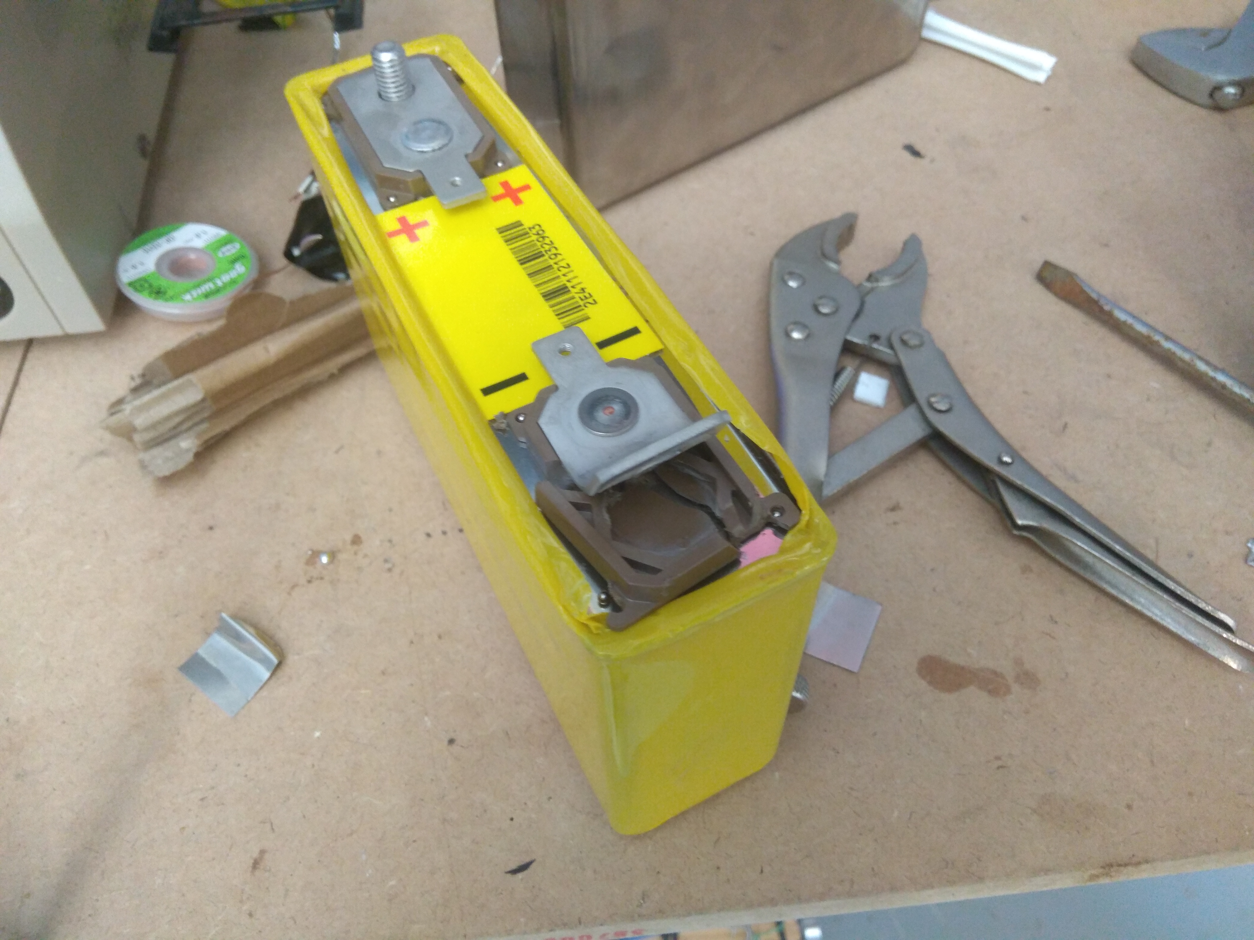
(Be careful when tightening the bolts that hold the busbar in place, that just some heat resistant plastic (bakelite?))
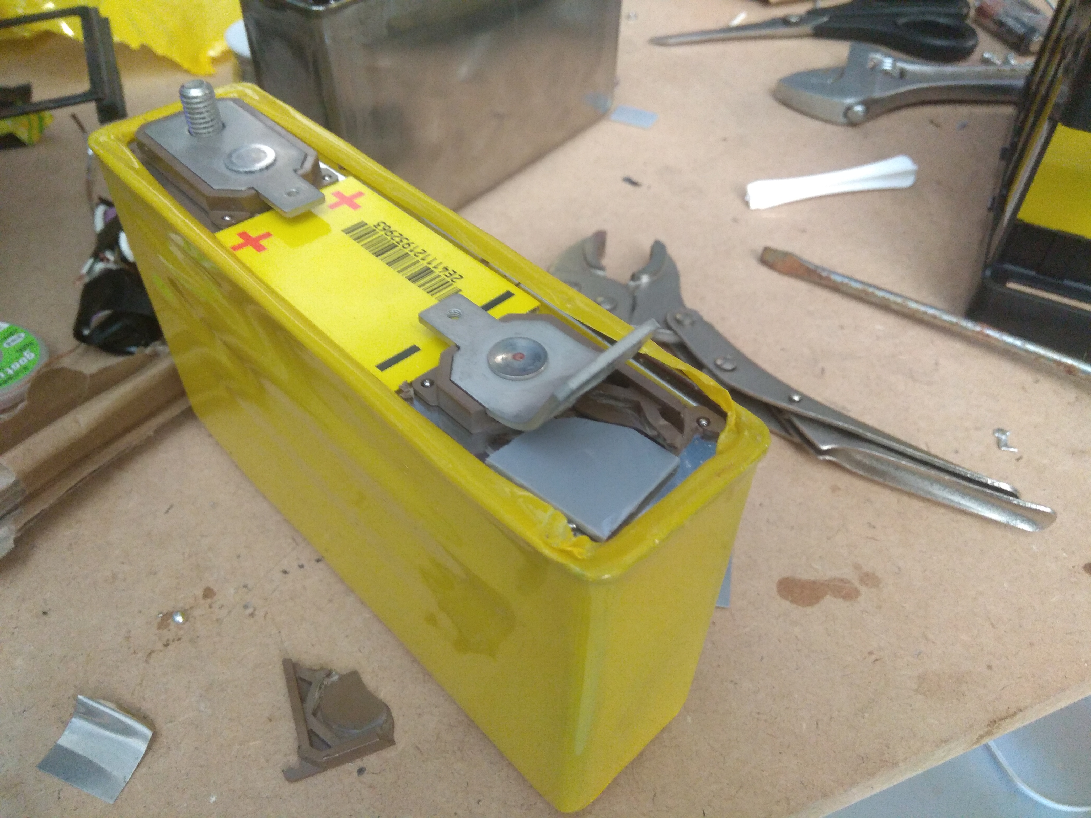
(We had to replace the plastic underneath because the case appears to be neither body positive nor body negative and we didn't want accidental shorts)
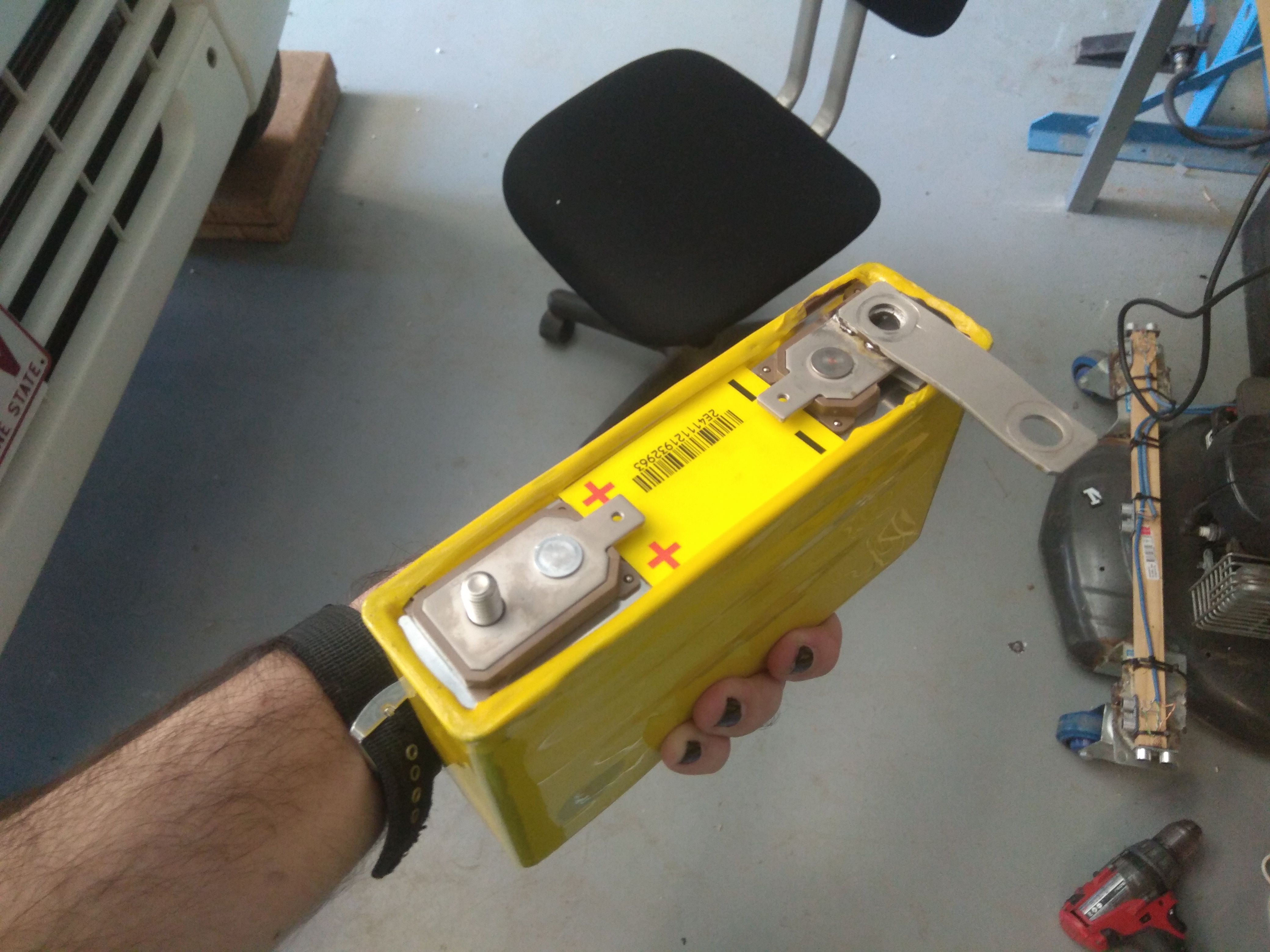
(After soldering the busbar back in place everything fit back together fine. It will make it a little more difficult to work with this pack in future as it means I have to completely disassemble it before I can remove any of the cells.)
Results
The first thing I'll mention is that so far everything has been going well (since I replaced the bolts and the balance boards we killed). The cells have held up fine and there doesn't appear to be any degradation going on with the new cells from their treatment. Unfortunately, they're also not giving me anything near 40Ah. In fact I seem to be getting something close to 20Ah, but the BMU is taking a while to adjust down. I think there are a couple of reasons this might be happening.
Firstly, I'm a little suspicious of the rating given on the Taobao listing. I wouldn't be surprised if I've bought cells that are 30Ah at 1C discharge and 40Ah at 1 amp or something like that.
Secondly, since the iMiev BMUs only work from 3.60v to 4.10v and the capacities listed for the battery seems to be measured from 2.75v to 4.20v I'm pretty sure there's going to be about 10% to 20% loss in "usable capacity" as measured by the car.
Thirdly, I'm being held back a little by one of the cells hitting full charge first and this meaning the other cell reaches empty first. Once I get a chance to check the balancing lead I'll have to see if that makes any sort of noticeable difference.
Finally, I think there's a calibration issue either caused by trying to voltage match the cells before they were installed (so the BMU isn't sure how much capacity it actually has any more) or by a difference in voltage curves for different lithium battery chemistries. The calibration issue makes some sense to me because when I took the old cells out, they were very nearly dead and nearly a third of a volt lower than the rest of the cells. When I installed the new cells I had to put about 10-15Ah into them to bring them as close to being in balance with the rest of the cells as I could. This might mean that the BMU doesn't know about those extra Ah at the bottom. I've noticed my car seem to go into turtle mode when the last cell hits about 3.67v under no load (maybe around ~3.5v under full load) and thinks it has about 2.5Ah remaining, both of those seem a little wrong to me. The other option is the difference in voltage curves, this one is based on the idea that the "Amp hours remaining" value given out by the BMU is calculated based on the voltage of the pack each time the car starts up and then is tracked based on current draw during driving until the car is started again, and then the process starts again. I might sound a bit odd, but I've noticed that if I charge the car to full from turtle mode (~2Ah remaining) I'll put in about 6kWh. This works out to be ~17Ah, but the readings from the BMU will say ~25Ah total capacity and ~22Ah remaining (meaning the car thinks I've put in an extra 3Ah). If I drive home and end up with ~15Ah remaining and everything seems fine, then I'll come back to my van the next day and suddenly find I'm down to ~9Ah remaining. There doesn't appear to be any self discharge occurring, all the cell voltages are still the same and it doesn't appear to drop in capacity if I drive around for a bit and then come back a day later. This change also shows up as a mysterious drop in range despite the car sitting stationary. (There's also a possibility that the program I'm using, HOBDrive, calculates the remaining capacity itself but that wouldn't explain the drop in range.)
Other than that, I appear to be getting quite a few cell errors pop up when driving but they're very random as to when they occur. Sometimes I'll get one every minute or so, other times I'll get one or two every 30 minutes. The appear to be messages about individual cells being out of balance, but I can't remember their individual codes right now. Obviously I also get a pack balance error due to the new cells ending up being more than 0.10v out of balance with the rest eventually.
Appendix: LEV50 body
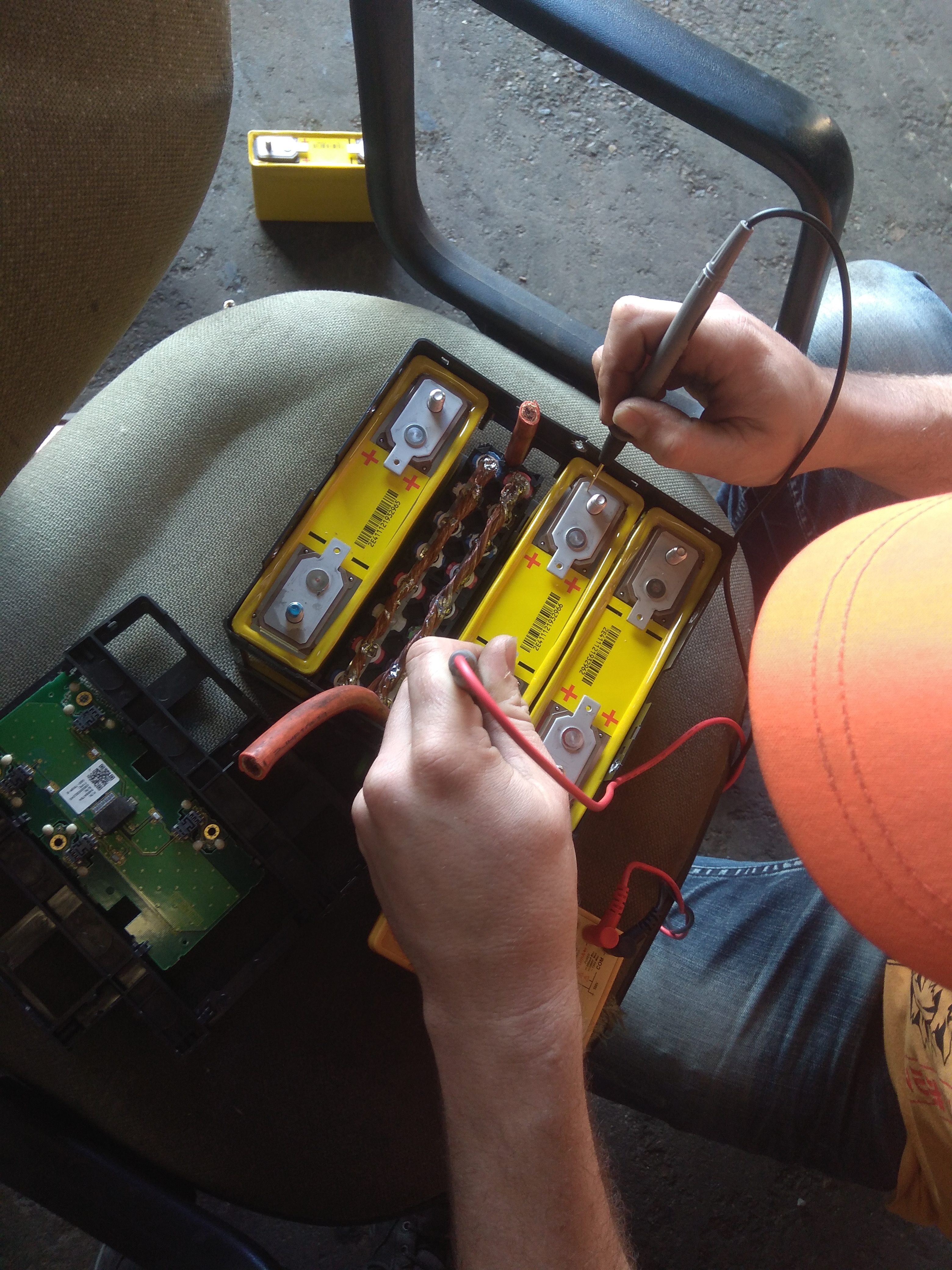
When we were fixing the terminal that had the seized bolt we wanted to double check whether the battery was body positive or body negative before we bent the terminal back into place, just to make sure we weren't going to short anything. It turns out the battery is a little over half way positive. This is the first time I've seen something like this and I'd be interested to see if anyone else has noticed this. We checked it on a couple of cells and the all came back about the same. I don't think it would come up much, but be careful not to short either of the terminals to the body.
Hopefully I've explained things clearly enough and there aren't too many typos. If there's anything that needs clarification let me know.
TL;DR: I swapped some dying cells out with aftermarket replacements from China and things mostly worked. Packs of 18650s can be used, but I wouldn't recommend it.
Band aid fixes and recommendations for pack removal
The first fix as a bunch of 18650 cells that were recovered from laptop batteries and had their capacities tested to try to match it to the other cells in the pack. I won't go into this fix too much other than to say it held up surprisingly well until the inevitable happened about a month or two later and the pack of 18650s eventually started dying too (who would have guessed that laptop batteries don't like being discharged at 1C with peaks up to 2.5C? :roll: ).

(Note the 18650 pack in the bottom right corner)

(Yes, it is held together with electrical tape and connected through welding cables. What else did you expect?)
Thankfully, by the time the 18650s were starting to become very unhappy another cell in the pack also started dying. So, now with two dying cells I decided to do the smart thing and grab some aftermarket 40Ah cells from Taobao (the rest of the LEV50 cells in my car are around 37Ah last time I was able to see full pack capacity). I also bought a 70Ah cell for my friend to use and to compare sizes against the LEV50s in my van.
Dropping the pack wasn't too hard since I'd done it before when I installed the 18650 pack, but I definitely recommend using a car hoist if you have access to one, but we made do with a couple of jacks, jack stands, some wooden blocks, and a pallet jack (though any kind of dolly can work). (If you're looking for a how to guide, check out https://www.speakev.com/threads/c-zero-battery-pack-repair.137750/) It would especially help to use a car hoist if things go wrong and you end up having to install, remove, and reinstall the pack several times because you either forgot to do things or things weren't connected properly!
Preperations for replacing the cells
It might not seem obvious if you've never stuck your head inside an iMiev battery pack, but there are a couple things you need to do before you can actually connect the new cell into the pack. Obviously there's the simply stuff like balancing, but there's also things like terminal connections and spacing, balancing connections, and cell packing. I'll try to deal with each one separately.
Firstly, the terminals on LEV50s have captive M8 bolts which connect to the bus bars between the cells. All of the batteries that I could find from China do not. So you'll need to make your own terminals. For this we used some 5/16" (I think?) brass threaded rod cut into short pieces, some annealed copper pipe which was crushed flat, and some brass nuts to suit the threaded rod. We crushed the pipe flat, tapped it for 5/16" thread, then screwed in short sections of threaded rod and soldered it in place. Then we soldered our home made bolts into place on the terminals of the batteries. The batteries we bought came with small tabs that I think ended up being zinc coated stainless steel. We removed the tabs beforehand because we didn't need them and wanted better contact between our bolt and the terminal.

(The replacement cell is significantly smaller than the original cells. Possibly suggesting that it's not actually 40Ah after all. We also removed the tabs that you can see bent over the sides of the battery.)

(Our little home made bolts. They were surprisingly easy to fabricate when you know a guy that used to run a sheet metal fabrication shop

(Soldering took a bit of work, there's quite a bit of thermal mass to draw heat away from the bit you're trying to heat up. Don't mind the black goo, it is liquid electrical tape)
When it came to terminal spacing it worked out really well, the spacings of the terminals turned out to be close enough to the terminals on the LEV50s that we could just position the bolt in the right place on the terminal. If you need to extend the bolt past the end of the terminal I'd probably recommend using longer sections of the annealed copper tubing to get it in the right place.
The next issue is the balancing leads. On the LEV50s in the iMiev, the balacing board screws directly on to one of the terminals of the cell itself with an M3 (I think?) screw. Unfortunately, the cells from China don't come with any tapped points on the terminal and we were unwilling to take the risk of trying to tap directly into the terminal. So what we did was take a small length of wire, solder one end to the the correct terminal, solder the other end to an M3 bolt then thread it through the hole in the balacing board and hold it in place with a nut. This seems to have worked successfully for the most part (more on this later). (No pictures of this section, it was done pretty late at night and we were done for the day)
Finally, packing. Since the new cells and the LEV50s are of a different size you'll need to make sure that the new cells can will be kept in place without putting any stress on the balance board or the tabs of the other batteries. For this project we ended up using spray foam insulation since it expands pretty well to fill the space and sets pretty hard to hold everything where it needs to be. Initially I was going to just use bits of corrugated cardboard, but ended up being talked out of it. I'm pretty happy with how it has held up so far. I've driven a little over 1000km since putting in the new cells (including some very harsh speed bumps in a school and a university) and everything has held up fine. The only thing I'd mention about using spray foam to hold stuff in place is that it makes and future service work pretty much impossible without having to ruin the foam.

(There's quite a bit of spill over from the foam. We ended up cutting it away at one point in the hopes of speeding up the curing process. I think since there wasn't much surface area exposed to air it made it take a lot longer to set)

(You can see one of the replacement cells in the bottom right where the old 18650 pack was sitting. The other is covered by the disconnect busbar, it's right next to the length of foam.)
Issues encountered along the way
Everything seems to be going fine so far. There was a bit of a problem initially, mainly caused by me forgetting to install a couple of bolts when putting the battery back together which resulted in one of the cells disconnecting entirely and the van having to be towed back to a friends house and spending nearly three weeks in his shed.
I spoke a little earlier about having an issue with the balancing. Basically, one of the new cells is not being correctly balanced. It's not out by much, but the cell is consistently 0.035v higher than the other replaced cell, and is always the first cell to reach 4.10v (full charge as far as the BMU is concerned). This is mainly an issue because the two new 40Ah cells aren't really giving me that capacity (more on this later too). I think maybe the balance lead has come loose (it wouldn't surprise me if I hadn't tightened it properly when we first assembled the pack) however I haven't had a chance to drop the pack again since I've started getting suspicious about how this cell is out of balance.
One final issue that was due to the previous repair attempt is that one of the nuts seized onto the threads of the captive bolt on the cell next to the one that was replaced with 18650s. When we re-attached the bus bar we probably over tightened the nut and it ended up welding itself in place. When I went to undo the nut I broke the plastic holding the bolt captive and it began to spin freely. We ended up fixing this by bending the terminal up, cutting the bolt free, replacing some plastic beneath the terminal. We then bent the terminal back into place and soldered the bus bar in place. It's not an ideal solution, but it works.

(Be careful when tightening the bolts that hold the busbar in place, that just some heat resistant plastic (bakelite?))

(We had to replace the plastic underneath because the case appears to be neither body positive nor body negative and we didn't want accidental shorts)

(After soldering the busbar back in place everything fit back together fine. It will make it a little more difficult to work with this pack in future as it means I have to completely disassemble it before I can remove any of the cells.)
Results
The first thing I'll mention is that so far everything has been going well (since I replaced the bolts and the balance boards we killed). The cells have held up fine and there doesn't appear to be any degradation going on with the new cells from their treatment. Unfortunately, they're also not giving me anything near 40Ah. In fact I seem to be getting something close to 20Ah, but the BMU is taking a while to adjust down. I think there are a couple of reasons this might be happening.
Firstly, I'm a little suspicious of the rating given on the Taobao listing. I wouldn't be surprised if I've bought cells that are 30Ah at 1C discharge and 40Ah at 1 amp or something like that.
Secondly, since the iMiev BMUs only work from 3.60v to 4.10v and the capacities listed for the battery seems to be measured from 2.75v to 4.20v I'm pretty sure there's going to be about 10% to 20% loss in "usable capacity" as measured by the car.
Thirdly, I'm being held back a little by one of the cells hitting full charge first and this meaning the other cell reaches empty first. Once I get a chance to check the balancing lead I'll have to see if that makes any sort of noticeable difference.
Finally, I think there's a calibration issue either caused by trying to voltage match the cells before they were installed (so the BMU isn't sure how much capacity it actually has any more) or by a difference in voltage curves for different lithium battery chemistries. The calibration issue makes some sense to me because when I took the old cells out, they were very nearly dead and nearly a third of a volt lower than the rest of the cells. When I installed the new cells I had to put about 10-15Ah into them to bring them as close to being in balance with the rest of the cells as I could. This might mean that the BMU doesn't know about those extra Ah at the bottom. I've noticed my car seem to go into turtle mode when the last cell hits about 3.67v under no load (maybe around ~3.5v under full load) and thinks it has about 2.5Ah remaining, both of those seem a little wrong to me. The other option is the difference in voltage curves, this one is based on the idea that the "Amp hours remaining" value given out by the BMU is calculated based on the voltage of the pack each time the car starts up and then is tracked based on current draw during driving until the car is started again, and then the process starts again. I might sound a bit odd, but I've noticed that if I charge the car to full from turtle mode (~2Ah remaining) I'll put in about 6kWh. This works out to be ~17Ah, but the readings from the BMU will say ~25Ah total capacity and ~22Ah remaining (meaning the car thinks I've put in an extra 3Ah). If I drive home and end up with ~15Ah remaining and everything seems fine, then I'll come back to my van the next day and suddenly find I'm down to ~9Ah remaining. There doesn't appear to be any self discharge occurring, all the cell voltages are still the same and it doesn't appear to drop in capacity if I drive around for a bit and then come back a day later. This change also shows up as a mysterious drop in range despite the car sitting stationary. (There's also a possibility that the program I'm using, HOBDrive, calculates the remaining capacity itself but that wouldn't explain the drop in range.)
Other than that, I appear to be getting quite a few cell errors pop up when driving but they're very random as to when they occur. Sometimes I'll get one every minute or so, other times I'll get one or two every 30 minutes. The appear to be messages about individual cells being out of balance, but I can't remember their individual codes right now. Obviously I also get a pack balance error due to the new cells ending up being more than 0.10v out of balance with the rest eventually.
Appendix: LEV50 body
When we were fixing the terminal that had the seized bolt we wanted to double check whether the battery was body positive or body negative before we bent the terminal back into place, just to make sure we weren't going to short anything. It turns out the battery is a little over half way positive. This is the first time I've seen something like this and I'd be interested to see if anyone else has noticed this. We checked it on a couple of cells and the all came back about the same. I don't think it would come up much, but be careful not to short either of the terminals to the body.
Hopefully I've explained things clearly enough and there aren't too many typos. If there's anything that needs clarification let me know.
TL;DR: I swapped some dying cells out with aftermarket replacements from China and things mostly worked. Packs of 18650s can be used, but I wouldn't recommend it.


