Swapping OBC's as diagnostic - safe?

Mitsubishi i-MiEV Forum

Help Support Mitsubishi i-MiEV Forum:

This site may earn a commission from merchant affiliate links, including eBay, Amazon, and others.

jpr

Member
Joined
Nov 8, 2022
Messages
23
Location
St. Paul, Minnesota, United States
Hi,

I have 2 i-MiEV's - both 2012 model year (North America). One is my daily driver, works great, charges (doesn't have Chademo), everything. The other I bought with a nearly dead main battery and not charging, although it will start and drive around in turtle mode. I have not been able to test if Chademo works (should've stopped by a station while trailering it home... durr), but it is equipped.

The problem car does not have any relevant codes - it had one for the battery fan (P1A2D), which I replaced, and that code has not recurred. It still doesn't charge though.

I've followed the troubleshooting steps in the Russian manual and believe the OBC is faulty. I removed the OBC and have not located any blown up capacitors or areas that look suspicious like in the main OBC troubleshooting thread.

My question is this - can I safely transplant the OBC from my good car into the problem car to check if that is indeed the problem? Or is there a risk of destroying the known good OBC? I figure if I transplant OBC's and everything works, I'll try and buy a good used OBC and call it a day - sell the bad one for parts perhaps on the forum. If I transplant and it *doesn't* work (and/or I swap them both and the good car charges with the problem car's OBC) then I have another data point for my diagnosis.

Worst case - I do have other cars I can drive if I render these both inop, but these are my only 2 EV's.

Thanks everyone =)
 
No problem in swapping OBC--they are not VIN coded.

do the white ceramic resistors measure thru for the L and N lines to the waffle plate solder junctions--that is a common failure.

Also is the MCU fuse intact (under the little access cover plate)? also the AC input fuses in the EMI filter housing and on the upper control board AC section?

If the path for the AC is interrupted then the charger will never "start" as it is waiting to see the AC after the EVSE has been given the go command; the EVSE must be okay since it works with the other car.

Of course a good strong 12V battery is required.

If no DTCs then that points to a lack of AC getting into the waffle plate to initialize the charge starting sequence.

If AC were getting thru then there would be DTCs thrown if something was failed in the OBC.
Thanks for the quick reply! I was more curious about whether I could damage the OBC as I know they're not VIN coded - but it sounds like that's not the case either?

I'll check the ceramic resistors shortly - I'm just looking for continuity from the L and N in the doghouse through to the waffle plate solder junctions, right?

MCU and AC input fuses are all checked and good. 12V batteries were swapped and both work equally in the good car.
 
do the white ceramic resistors measure thru for the L and N lines to the waffle plate solder junctions--that is a common failure.
I think we found it. I took readings, and as I understand it found one good one bad, noted in the attached photo.

I assume what I need to replace is one of the guys I've circled in green - and that to do that I need to do the dreaded waffle plate de-solder and removal 😬 - correct? I'd scrape off the potting, replace the affected resistor with one of similar spec (I'm browsing the forum and haven't found a guide or part number yet), and put everything back together.
 

Attachments

  • Screenshot 2024-07-17 at 4.48.30 PM.png
    Screenshot 2024-07-17 at 4.48.30 PM.png
    534.6 KB
So both of your ceramic resistors are okay by that measurement of 10.6 Ohms from the white wire over to the solder junction marked "N".

The black wire should/will have direct continuity over to the 1st row of solder junctions marked "L", not the blue circled junctions in your photo.

No need to try to de-solder the 72 joints of the waffle plate just yet.

you may want to check the diode drop voltages of the waffle plate, especially the upper left corner section with the diode rectifier bridge--that could be another show stopper for AC getting in to the PFC stage section which is the detector circuit for AC present.
Link to full sized diode drop voltages

[edit: check for dirt or debris or ants nest down inside the charge socket--maybe something is clogged in there and no path for the AC?]
 
Last edited:
Okay, the black wire to the (correct) L trace does have continuity, thanks for catching that!

I'm struggling on how to check the diode drop voltages. I don't have a means of pushing voltage to the board (and I'm not 100% certain where it'd go) but I did find this image which matches my D505-D509, which all check out as I would expect (i.e. the diodes are open one direction only except 505 and 507 which have resistors in parallel, and those measure ~180 ohms which seems fine).

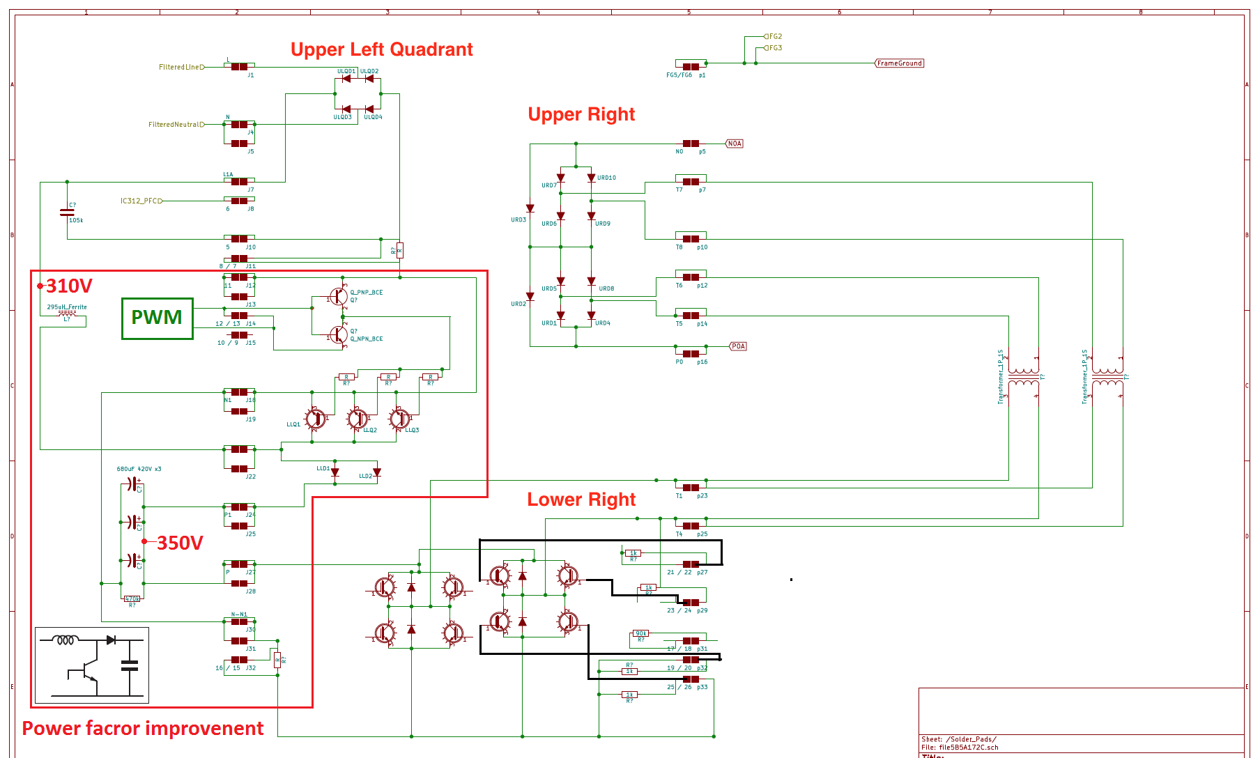
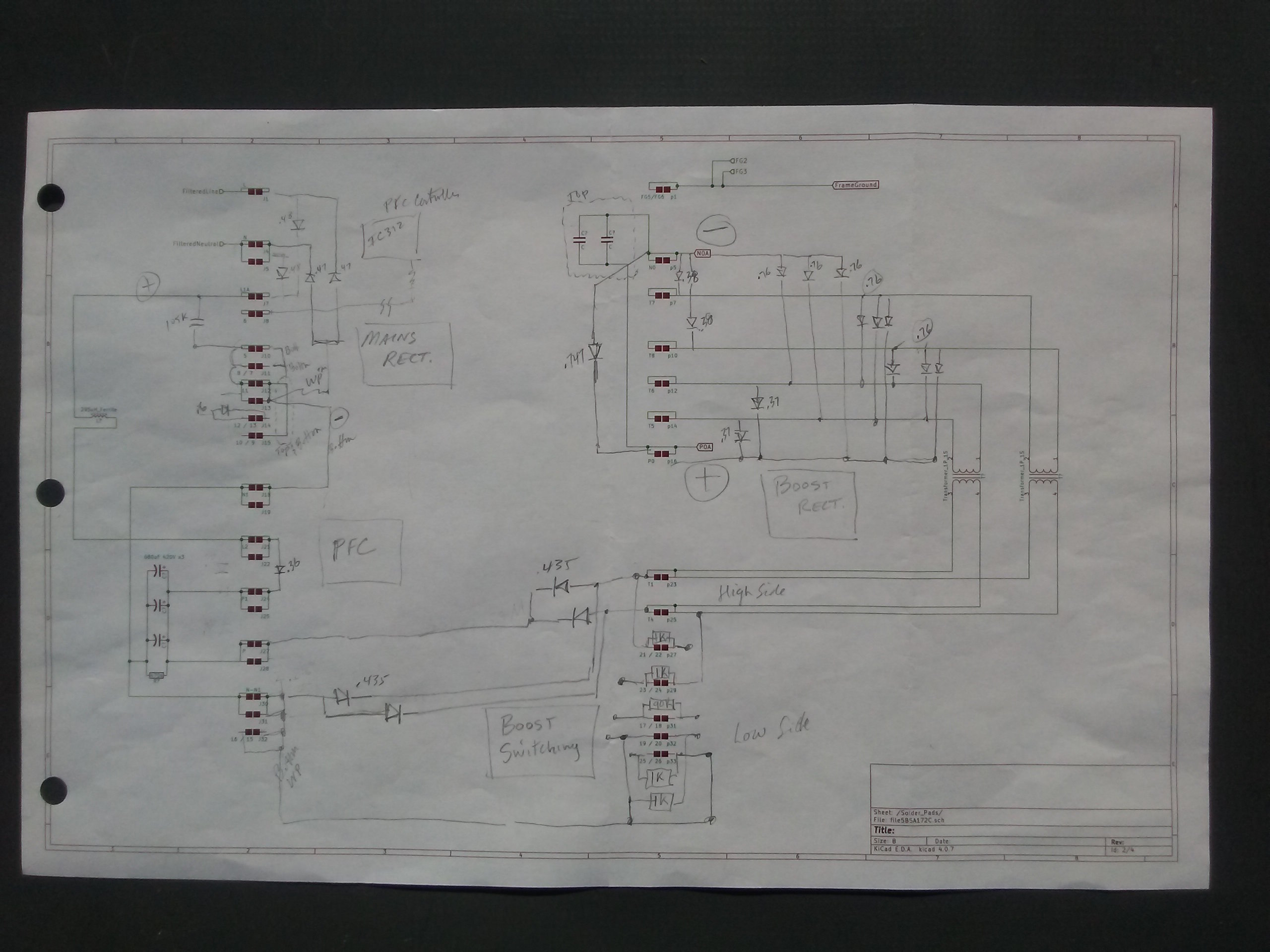
That said, I don't think this is the rectifier bridge of which you speak. Looking at coulomb's diagram which actually has the expected voltages labeled I don't see anything that matches the (admittedly highly pixelated) labels I think I can make out - which start with UL00.

I inspected the charge socket and it's clean.
 
Unfortunately the updated forum software threw off all my page referenced links in the OBC Troubleshooting thread, and some pictures are not showing or linked properly.

Here is a schematic of inside the waffle plate showing the diodes that can be checked using a DMM with the diode check function. The labels were made up by me since everything is covered in black epoxy.
Waffle Plate

107222143d286838e3b7b7213d00142b.png


Here is my original diode drop voltage measurements using DMM and touching the leads to the waffle plate solder junctions, from post #41 on page 3,
7a64afabac95f21b9719d4a3895010d6.jpg


You have to give many thanks to coulomb for cleaning all this up and showing the voltage drops and where to put the red + and black - probes, along with some resistor values to check, link to full sized version link to full sized version

Waffle plate diode drops Coulomb.png
 
Last edited:
Looking at coulomb's diagram which actually has the expected voltages labelled I don't see anything that matches the (admittedly highly pixelated)
Arrgh - there is a bad link to the good image, and now I can't edit it.

Here is the good link: https://forums.aeva.asn.au/download/file.php?id=6753

@kiev, could you fix the link with your new moderator powers? The page in question is here; bad link at the top right.
[edit: i think it's fixed, please test and let me know--this is my first edit as a mod for something like this]
 
Last edited by a moderator:
Finally got around to checking the diodes in the upper right and upper left parts of the OBC... and everything seems to check out according to coulomb's diagrams.

Starting to think it may be time to swap OBC's and see if I'm barking up the wrong tree entirely with the OBC, here
 
The car does go into Ready mode and can move so I doubt the CMU specifically is bad - but I'm not finding anything wrong with the OBC either.
A CMU can transmit faulty data intermittently, during driving this may merely flag the tortoise light but as experienced by @alviseven, low voltages will prevent/stop a charging session immediately.

Did you ever monitor your cell voltages while trying to charge ?
 
My car went into ready mode and drove - still does but it became increasingly hard to charge and eventually only got to chademo to charge it then even after that stopped.
I have replaced cells from a scrap car but had to reuse the green CMU boards and when back together still did not charge and still had battery fault but also still ready mode and moved.
Changed the CMU09 faultly board initially for a red board which worked by the way and then put the repaired CMU09 board back in the pack which also worked. However now once again getting a fault with the same CMU09 which does clear using the DTC clear function on Hobdrive - can even do this on the move by my passenger on the move. However the tortise does not often come on either.
However the charger on my car was changed for the one from the spare and both work now once the CMU fault was cleared up - never had a charger issue in the first place. Like you took my charger apart to find that there was nothing looking amiss with it and all looked good.
I find that the CMU that is playing up has a voltage value on the readout that drops and rises - from the main pack voltage eg 4.10v to something silly like 0.75v and then back up again - also sometimes get a jolt in the drive along road before the battery light comes on almost like a pre fault experience if these indicators sound familiar to you?
Currently looking for a spare green CMU09 board too!
 
Did you ever monitor your cell voltages while trying to charge ?
I haven't yet - I did load up all the cell voltages with my scan tool and they were all consistent to a couple mV. The pack is at a very low SoC though, so I wonder if that could be preventing a charge if one of the CMU's is intermittent as you describe.

@alviseven thanks for sharing your experience! That's very enlightening. I don't have many data points as I bought this car non-running and the previous owner wasn't very communicative. I'll get a look at live voltages when I have the car back together and see if anything pops out the way you mention.
 
Well, I finally reassembled this OBC because I couldn't find anything wrong with it, swapped it into the good car, swapped the good car's OBC into the bad car... the good car charges with the "bad" OBC, the bad car doesn't charge with the "good" OBC.

I think I may try towing it to a Chademo. Threw out my back swapping chargers though, so it'll be a while.


Write your reply...
Back
Top