i-MiEV Not AC Charging, (Was No DTCs), 12v dc-dc OK

Mitsubishi i-MiEV Forum

Help Support Mitsubishi i-MiEV Forum:

This site may earn a commission from merchant affiliate links, including eBay, Amazon, and others.

JoeS

Moderator
Staff member
Joined
Dec 15, 2011
Messages
4,436
Location
Hills above Silicon Valley, California
Thought I'd start a new thread regarding the troubleshooting process whereby, after the charging plug is connected and the vehicle attempts to charge but the (perfectly good) charging station shuts down after a few seconds.

I just installed a brand-new OBC without a doghouse to replace my previous doghouse OBC which is still undergoing repair for the usual failure(s). I had replaced the blown HV fuse in the MCU. This new OBC nameplate identifies it as NAS, V100, ZHTP1581R, Serial.00001 :!: , dated 2012.04.26

My North American i-MiEV with CHAdeMO there is the usual 'whoosh' (battery fan ) when the car is first plugged in using J1772 , the 12v jumps up to 14.4vdc (indicating the dc-dc portion of the OBC is working), but after about four seconds the EVSE relay clicks and 'charging' stops.

Edit 7 October 2022
WAS: No DTCs or warning lights.
IS: DTCU111D and warning triangle with exclamation point flickers on briefly when car plugged in

CHAdeMO charging works just fine.

With the EVSE unplugged, the car goes into READY with no warning lights and the car runs just fine, the battery happily sitting at ~14.4v.

I need to listen carefully some more as I thought I heard a relay click in the car at about the same time that the EVSE relay clicks to shut down.

My first thought was to build or buy a J1772 breakout box and monitor its signals, but I welcome any and all suggestions on how to approach troubleshooting this problem. TIA
 
Sound, let’s look at the other side then, apart from the resistor on pin 5 (CP) the car’s connector is directly wired to the OBC, assuming charging was working beforehand then your replacement doesn’t seem to be working properly.
 
-
MickeyS70, thank you for your help. Sorry for my slow response.

With the car turned off, taking resistance readings of the Control Pilot (Edit: correction, this is Proximity Pilot) to ground at the car's J1772 inlet, both of my i-MiEVs read close to 800Ω.
MickeyS70 said:
... assuming charging was working beforehand then your replacement doesn’t seem to be working properly.
That's an understatement, :) but at least the 12vdc-dc is working.
 
This problem might be not be OBC related: the iMiEV workshop manual has a different pinout to the official J1772 standard, so I was wrong: CP communication is managed directly by EV-ECU.

Apart from AC, only PP is going to the OBC, you can test it with ignition on, it should measure around 4.5Vdc.

There is no doubt that your original OBC was faulty but the fact that the new one doesn’t charge either may suggest that your EV-ECU has issues also?
 
MickeyS70 said:
This problem might be not be OBC related: the iMiEV workshop manual has a different pinout to the official J1772 standard, so I was wrong: CP communication is managed directly by EV-ECU.
Thanks for noticing this, as I hadn't looked at the manual yet. :eek: Wow, this is getting muddled as the i-MiEV manual J1772 connector numbering and naming is different from the J1772 spec and it doesn't say which end of the car's connector one is looking at. Wikipedia shows names rather than pin numbers in its pictures, and of course we also need to understand which connector we are looking at - i.e., plug vs receptacle, and which end. Edit: Further confusing things, I *think* Wikipedia's table should show PP as Pin 5 (not 4) and CP as Pin 4 (not 5).

SAE wants $148 for a copy of their J1772 spec! :twisted: Some drawings scattered throughout the Internet also have pin numbering differences (sigh). Found another nice schematic in this Texas Instruments design guide (Figure 1), but no graphic of the connector itself identifying the pin numbering:
https://www.ti.com/lit/ug/tiduer6/tiduer6.pdf

My own 800Ω reading was, looking at the car inlet receptacle, lower right pin to bottom center pin, which I now see is the Proximity Pilot and not Control Pilot. I did measure 4.45vdc when I put the car into either ON or READY, verified on the other i-MiEV. Need to remember, the Proximity Pilot circuit does work because, when plugging in the car, it wakes up, the battery fan goes whoosh and it does start trying to charge...

MickeyS70 said:
There is no doubt that your original OBC was faulty but the fact that the new one doesn’t charge either may suggest that your EV-ECU has issues also?
Perhaps, but I need to read up a little more and extract the appropriate diagrams and put some thought into this before continuing... :geek:

Thank you for your help.
 
-
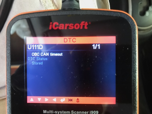
It turns out that I made a cockpit error and had not used my iCarSoft i909 correctly, as I indeed do have a DTC recorded;

iCarSoftOBCDTC.jpg


Reset the DTC, the car still won't charge, and the DTC came back.

According to the MMNA service manual Section 54D-350 this is a communications issue between the EV-ECU and the OBC, with probable causes being damaged harness or connector(s) or a malfunction of the OBC CAN data system.
I re-seated the OBC CAN bus connector (that sucker is difficult to access with the OBC installed), to no avail. Of course, the next step in the manual is to replace the OBC :evil:

Anyone have any ideas on how to troubleshoot that CAN bus without a MUT3? Anything else I can do with the i909?

Recall, this is supposedly a brand-new OBC.

Thankfully I can continue living with this problem as my home Setec CHAdeMO charger works just fine and we no longer venture far from home with the i-MiEVs due to charging station availability anxiety.
 
That's a good find Joe, it appears to be a real DTC in your case. Many times it seems that the U1xx CAN codes are caused by a low 12V starter battery.

Did you look under the rear seat to inspect the wiring harness around the EV-ECU? Also look for rodent damage on the exposed harness section under the car back to the OBC and inspect the brown-colored Junction Connector for CAN1 and CAN2. The OBC is on the CAN2 buss.

There are some resistance measurements that can be made at the connector pins, found on this page:
http://mmc-manuals.ru/manuals/i-miev/online/Service_Manual/2012/54/html/M154830250113000ENG.HTM
 
wmcbrine said:
JoeS said:
... we no longer venture far from home with the i-MiEVs due to charging station availability anxiety.
Is that due to worsening availability, or decreasing range of the cars?
Worsening availability - it seems to be hit or miss, with charging stations or CHAdeMO chargers occupied or broken. All CHAdeMO chargers are shared with CCS nowadays. What's especially vile is the number of (new) EVs treating these as parking spots in shopping centers without plugging in - my solution under their windshield wiper:
BlockedEVSE.pdf

http://www.katiekat.net/Vehicles/Mitsi/BlockedEVSE.pdf
Used to be we'd only take the Tesla for round trips over 100 miles, but nowadays find ourselves taking it on 50+ mile trips if we're short on time or don't have the ability to conveniently opportunity charge the i-MiEV during the trip.
 
Hi guys, I've got a similar issue where my 2010 MiEV won't detect that the charger is connected at all unless ON or READY, working DC-DC, no codes. This MiEV also seems to be a proximity pilot only version as there is no CP contact in the charging port.
The PP shows 4.5V when ON or READY, 0V when off and the resistance between ground and PP when off was ~1k ohms.
Continuity of the CHGP line between ev-ecu and obc is good, same with the PP and ev-ecu.
Not to sure what else I can test going forward, any pointers?
 
The 2010 OBC has similar functions but different boards than the 2012 version, so likely some differences in the connector pinout.

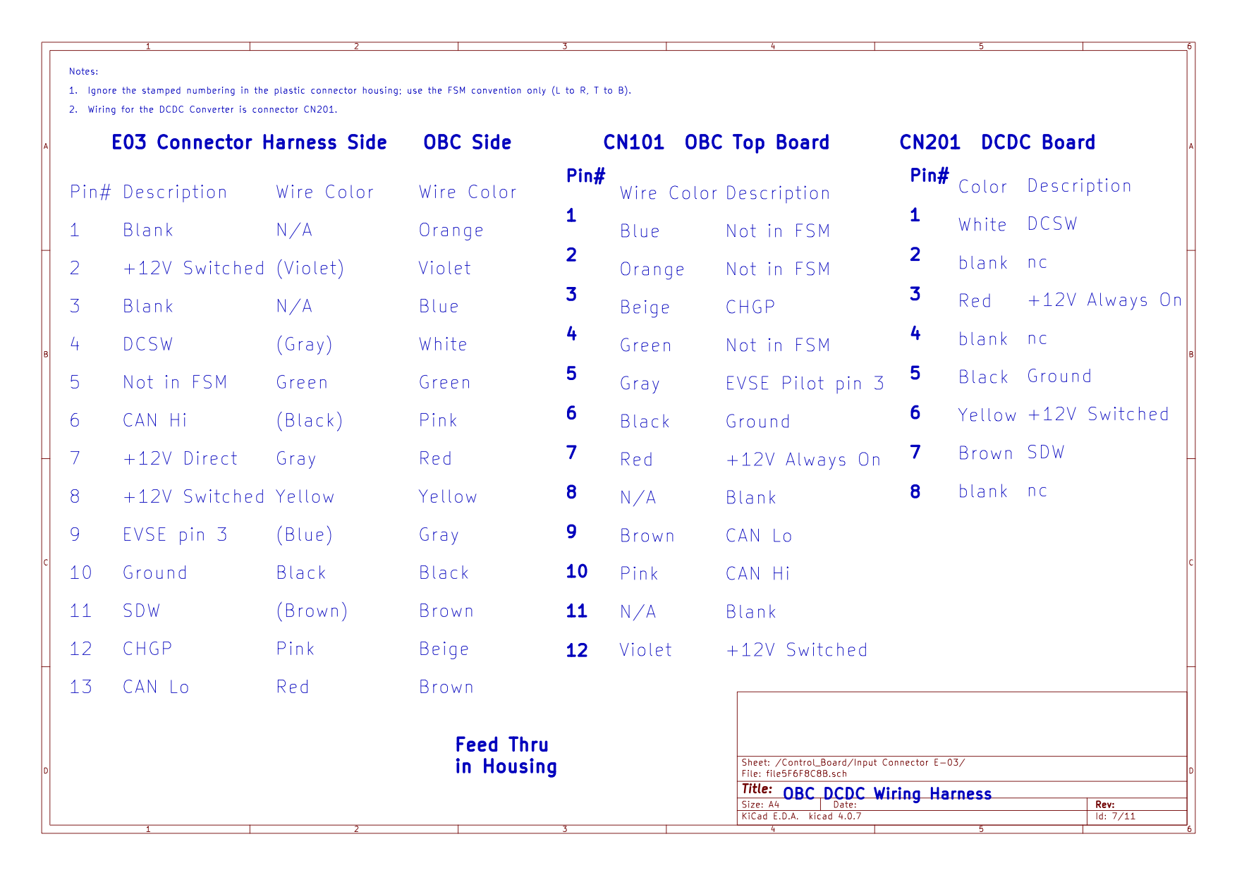
Here is the 2012 connector pinout for comparison, maybe there are common pin functions.
j8KrMsT.png


One thought i had was that one of the 12V feeds may be missing, e.g. the 12V Hot All the Time, or the 12V from the EVECU to wake up the OBC and initiate charging. The 5V supply for the PP signal has to be created from one of the 12V feeds; that feed seems not to be present unless you have the key ON or READY, which seems to be opposite logic to what it should do for safety protocol (to prevent driving away while plugged in).

Have you opened the OBC cover to see what code shows on the 1-digit LED on the top control board?
 
At CN101 the 12v Always on is present, but the switched 12v only seems to be triggering when ON or READY and the EVSE is plugged in, when it’s triggered the 1 digit LED shows a roughly 1hz flashing dot and the PFCPWM LED lights up.

There’s no wiring for “EVSE pilot pin 3” I’m guessing this is for the CP pin in newer cars.

Looking at all this it seems the PP voltage is generated in the ECU?
I should mention the PP voltage does drop appropriately when an EVSE is plugged in, although the EVSE itself never shows any charging or fault indicators.

I’m not sure how the car triggers the EVSE to begin charging without the CP pin, but could I somehow fool the EVSE into “charging” and supply 12v to the OBCs switched pin to see if charging initiates? Or would this cause the magic smoke escape.
 
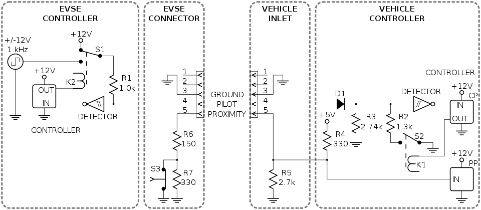
i better double check if there is a typo on that connector pinout, i used skylogger's notes way back in the OBC thread. The EVSE pilot pins are CP 4 and PP 5 of the J1772 connector, and Pin 3 is earth ground, not a pilot.
[edit: i see why it is the convention used by Mits, not the J1772 standard taken from wikepedia]

960px-J1772_signaling_circuit.svg.png


i wouldn't recommend trying to jumper anything unless you are sure about the effects and consequences.

Is your EVSE cable just a J1772 connector to the car with a cable and mains plug that you put into an outlet? If so then i think there is some small resistor circuit built in to the handle of the J1772 for the PP function.
But it is odd that there is no CP.

The EV-ECU is the real controller of HV charging.

Notice that E-03 has one Always Hot and 2 Switched 12V lines--do you have 2 switched 12V ?
Do the wire colors in your car match those of the pinout diagram for E-03? for CN101?

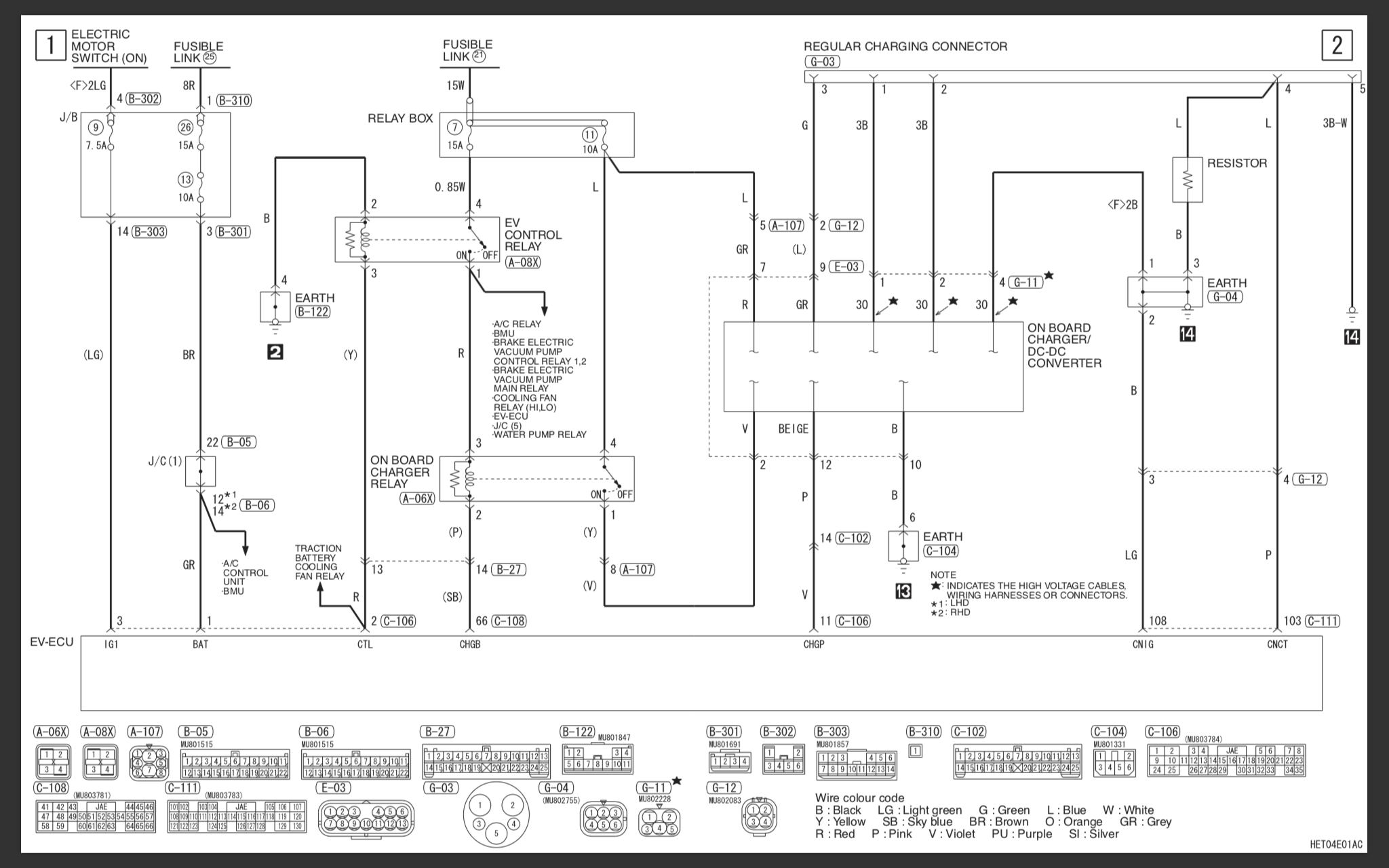
The switched 12V is supposed to come thru the EV-ECU, and it shouldn't require or allow it to occur with the key ON or READY, so you have a wiring issue, relay or fuse that is not working, etc. e.g. Fuses 26 and 13 below.

Here is the 2012 power supply and other signals for the OBC; notice they used their own convention for the CP and PP pin numbering at the charge port (not the J1772 standard)

OTrpvYX.png
 
Been a bit busy over the last few weeks but coming back to this now I've tested the 2010 OBC pin functions and it is quite different to the 2012 pinout diagram.


I am relatively new to EVs and had no idea there was such thing as a J1772 connector going straight into the wall, as this car is new to me and didn't come with its original charger silly me assumed it should just work on the EVSE equipment my other MiEVs use. But no!

Fabricobbled together a lead using an old J1772 lead to plug straight into a 15A mains plug and it worked!

Thanks for your help, now I know one more thing about these little cars I didn't know before.
 
Back
Top