2010 obc fail.....yep another

Mitsubishi i-MiEV Forum

Help Support Mitsubishi i-MiEV Forum:

This site may earn a commission from merchant affiliate links, including eBay, Amazon, and others.

686579

Member
Joined
Nov 30, 2020
Messages
10
2010 imiev, 80xxxkm, ac side of the obc.
hey all who read this 2020 claimed another beloved electric brick. while ugly and under appreciated my imiev is a valued member of the family and its hurting(was this many years old and didn't realise its un-named =O ) so any and all help to getting him...her..... it..... back on the road would be greatly appreciated.

symptoms were plug in ac it would cycle relays fans etc. about 10 seconds after switched on it would get a orange ( ! ) on the dash and turn off.
the battery is about a year and a half old and is a good brand name one etc. (currently testing at 13.5v....)


so pulling out the obc opening it up it blew the upright capacitor board. upon initial inspection. these were replaced. all known fuses checked.(including the small onboard one)
it was put back inside the car and i have the same issue.

following the trouble shooting and repair for obc post i checked resistances of the nutural of the middle board. found it sitting at 2.7-3 and that energising the relay made no difference.

so now looks like im about to join the attacking waffle plate(bottom board) group......

does anyone have a part list for what might be needed so i can get them ordered and ready to replace.
(relay and resistors )


any other things i have missed of ideas for testing let me know.
'
p.s. while handy with a soldering iron and a volt meter im no expert but also not afraid of learning new things(ive build custom drones-eskate-rc everything really haha) so far has been easy, but pulling off that wafel plate looks like its going to be a *insert swearword of choice*

(pic of blown upright capacitor board)
https://imgur.com/a/yCgLR6T
 
So the capacitor board in the black potted area is used on the HV DC Output side of the OBC; everything else in the potting is for the AC Input. Usually they fail one side or the other, although it is possible to fail both.

And also usually the 20A fuse under the cover plate of the motor drive inverter also called the motor control unit or MCU, will blow when the capacitor board blows. If that fuse has blown open, then the car will drive but won't be able to recharge the pack or recharge the 12V aux battery from the DCDC converter in the lower plenum of the OBC.

if it were mine i would want to do some additional measurements before removing the waffle plate, such as verifying that AC is actually getting to the top board, then to the bottom board, then whether or not it is reaching the L and N solder junctions on the bottom board, etc. Also measure the resistance of the relay coil, does the relay click when energized, etc.
 
Inverter fuse was checked. Inverter also visually inspected.

I did notice tody slight heat marks on the potting near relay and resistors and coil.(in dog house) they all visually look fine and I've started cleaning the potting out.
Will be checking nutural and life (black.white spades)
Tomorrow.

Is there any other places to check for power ? Pictures would help.
 
From your picture i can't really see the damage to the capacitor board, it appears to still have 4 caps in place. When that fails it blows the caps off the board and blows the inverter fuse.

Do you see any hairline fracture in the white ceramic resistors?

Do you have OBCII dongle and phone app to read the DTCs, or some sort of scantool to read the codes?

At this point it would be safer to just remove the bottom board and make resistance and diode measurements on the work bench. From the Black terminal to the L on the double solder junction i measured about 2 Ω, and from White to the N about 11 Ω.

i measured relay coil resistance at the D301 diode of about 69 Ω.
 
Kiev
The very bottom was blown out sideways. Lots of black stuff nearby

No hairline cracks but haven't cleared putty out yet.

No dongle that works. (Have a cheap.bluetooth one but yet to find. App.that works)

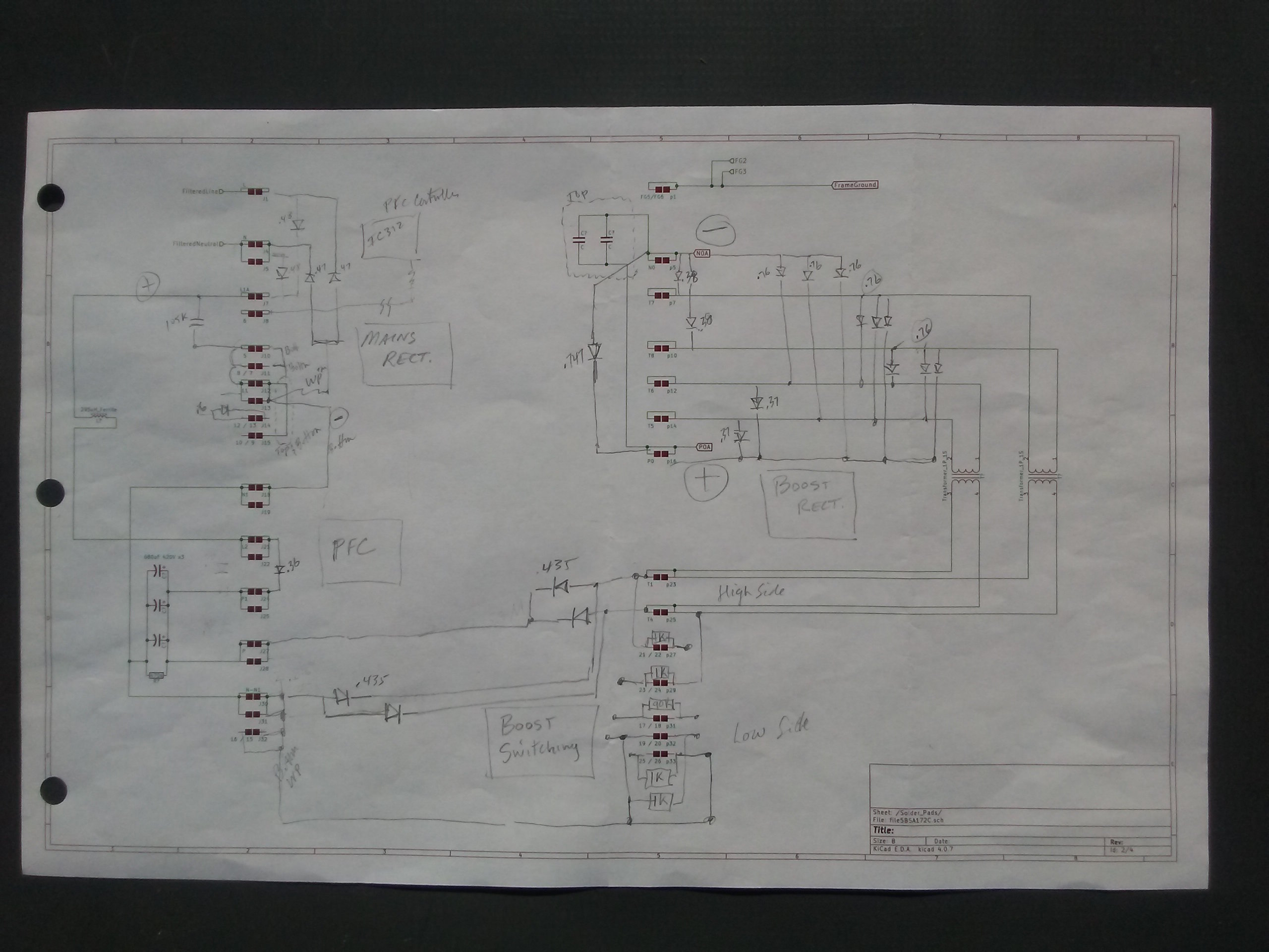
Resistance checks.
Black to L (on the white strip). No resistance (closed circuit)
White to nutural 9.5
Relay(both sides of diode 60
 
That measurement seems to indicate that the ceramic resistors are reading the right resistance.

When you say that something has blown out sideways with the black material--are you talking about the relay or the capacitor next to the resistors? A picture would really help.
 
that was in reference to the capacitor board.

there was heat scorching on the putty near relay and resistors. ive started to pull putty out but nothing found yet.

picture to come but nothing really to be seen
 
https://imgur.com/a/a3djB1i


i removed some putty already to look for damage, none able to be found as yet
 
It doesn't appear that you have any issues on the AC input section, based upon the picture and your measurement data. You need to get the OBC DTCs to get a start on where to look.

There is a clear coat material on the circuit board that can cause spurious readings if it is not removed at the measurement points.

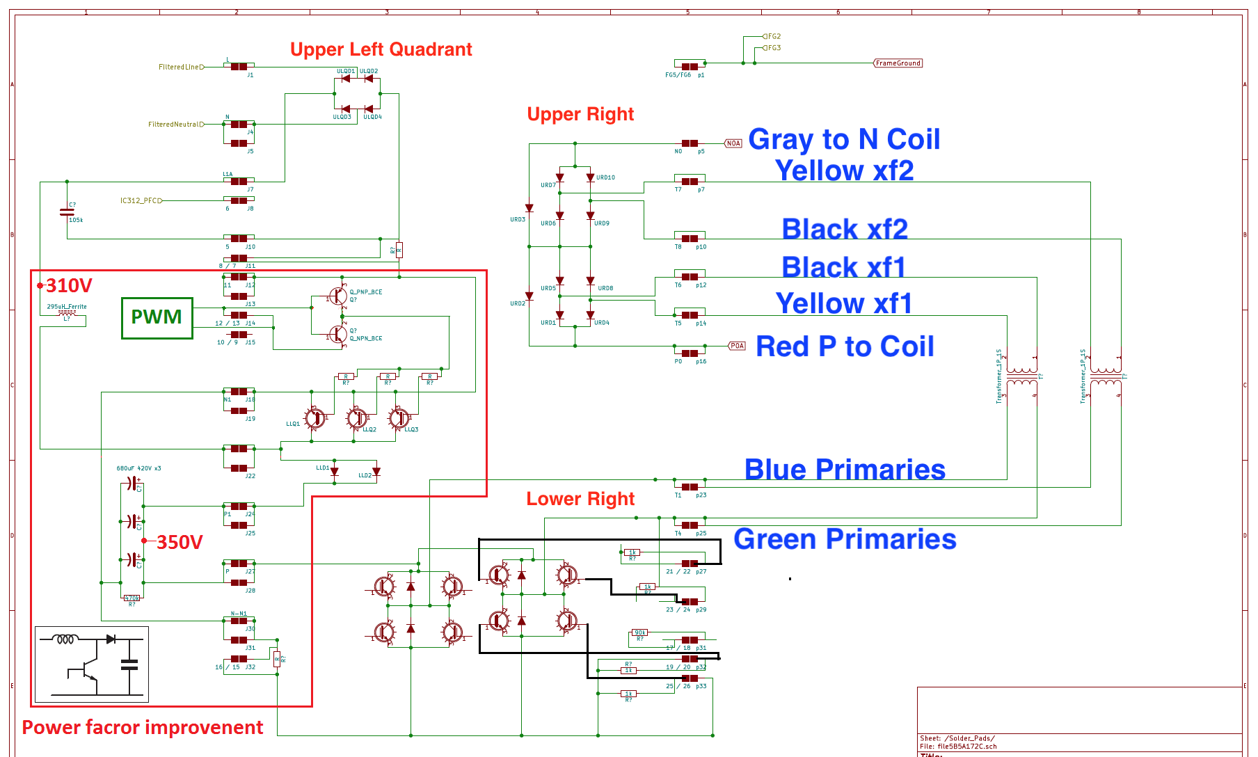
You might try measuring the diode voltage drops of the waffle plate, it doesn't have to be removed, only the faston tab connections removed. That is a rare failure mode, but it is easy enough to measure and verify its condition.

waffle plate diode voltage drops
VbRyfIb.jpg


pretty version with faston wiring
SBC5zA0.png
 
i was under the assumption my issue was at the relay, as when its energised, it has no reaction.
tho i will have to pull off waffle to correctly repair.

as for the below having a glance at it it seems straight forward but im also cautious in my ability to intemperate correctly. i suppose time will tell.

heading into town tomorrow does anyone have a link for the relay so i can hopefully find a replacement one.


cheers all for the help thus far. im getting excited to have my brick rolling again =D
 
686579 said:
i was under the assumption my issue was at the relay, as when its energised, it has no reaction.
tho i will have to pull off waffle to correctly repair.
A link to the relay datasheet is in post 2 on page 1 of the OBC Troubleshooting thread.

Did the relay not make click/contact when you applied 5V to the coil contacts? It's not clear from your previous notes that it was energized.
 
sory yes i tested the relay by checking resistance across nutural then i energised it with 5v as sugested, it made a click but no change in the resistance(it was a close circut, sugesting its a naturaly closed circuit ?)
 
686579 said:
i was under the assumption my issue was at the relay, as when its energised, it has no reaction.
Don't forget you need to get the polarity correct, else the diode there will short the power supply. Or if the power supply is strong enough (won't take much), it will destroy the diode. Having the diode not working will allow spikes of voltage to destroy other parts of the circuit.

You need to apply 5 V such that the diode doesn't conduct (positive to the stripe on the diode).

Edit: oops, didn't see your last post. If it clicks, you're probably applying power OK. If the relay clicks but doesn't short the pre-charge resistors, it needs replacing, obviously.
 
my plan is to hopefully pry it open, from the top, visually inspect, manually override while ac charging, to prove that's the only issue. if it is ill replace the relay. if not then the car haha(joking...not really )
 
more testing done, relay works resistors work. capacitors work(tho i would like to confirm how they would be checked i checked connection between polls and inverter cables. but im unsure where to check upstream)

the black capacitor and the resistors have no visible cracks or damage/
resistors checked ok.

im at a loss as to what to check next tho.... any ideas ?
 
Back
Top