Wrecked i-MiEV Battery Pack Discussion

Mitsubishi i-MiEV Forum

Help Support Mitsubishi i-MiEV Forum:

This site may earn a commission from merchant affiliate links, including eBay, Amazon, and others.
A

Anonymous

Guest
Thanks for sharing your insights on adding packs.
I'm offered a wrecked c-zero for 1.500$ and pretty sure I will take the offer.
So I'm thinking to play with connecting the battery pack to the iOn we've got and wondering where exactly is best to connect it so it charges from the level 1 (type 1) inlet/EVSE and also from the CHAdeMO inlet?
Do send a drawing if you can.

(Our iOn has QuickCharge CHAdeMO inlet.)

I'm also considering to split up the pack to fit as much as possible as close to the floor and center of the car as possible. Perhaps try and remove the rear seats for testing. Any experiences on most efficient ways also in terms of getting a level cargo floor?

PV1 said:
The i-MiEV will shut down if it sees too much power going into the battery during a normal charge. This threshold is pretty close to the max output of the charger (4 kW threshold on a 3.3 kW charger), I guess to protect the charger from overload.

Please help me understand this piece. Why will the charger output exceed 3,3kW (4kW) if connecting 2 packs?
So I might have a charger from the wrecked car. How do you suggest I wire this second one to the 2nd pack or all together, so the 2nd pack still provides power for the driving and charged fra QC CHAdeMO?
Do make a drawing if you can.

Concerning chargers from emotorwerks I have some unpleasant experiences with their 25kW DC charger. So I bought a 25kW DC unit, CHAdeMO controller and CHAdeMO DIY looking cable. First of all the CHAdeMO controller is unable to charge this car, only worked on Nissan Leaf and Nissan ev van.
Secondly, when connected to 3phase AC input it draws some 48A which caused the attached thermistors (working as inrush-current-limiters) to litterly burn off after a few charges of the Nissan causing some pretty dangerous situations with sparks and stuff. No wonder this happened as datasheet on the thermistors shows current rate at 35Amps.
Thirdly the DC charger seams to have damaged our Nissan battery pack so it now stops charging after barely a minute whether DC or AC charging. With specialist help we measured the output DC to contain more than 20% rippel AC around 87V AC. The specialists mentioned anything above 4% is extremely harmful to lithium batteries.
Fourthly the harmonic distortions of the charger are emence. We measured around 86% THD on full 25kW charge and about 120% when charging less. We found lots of currents flowing at 250Hz, 350Hz and up.. which is damaging to electronics, motors, compressors as currents flowing in 250Hz does flow in opposite direction creating breaking of motors and extra heat/wear in electronics.
In fact we discovered how our own instrument, a more simple one, measured the current flow in 250Hz due to the high distortion, when we would expect this to be measured in 50Hz (EU).
Fifthly we found the charger to have a powerfactor at 0,7 capacitive load meaning its having a huge capacitive load dragging a AC three phase star mains out of balance again causing derating on other connected equipment and failur.
I've brought this to the attention of the company who claims to have sold hundreds of them if not more.
However I have heard no response to my more than 10 calls and emails.
So now I'm stuck with a pollutive and destructive piece of DC charger and CHAdeMO Controller which is unable to charge this CHAdeMO ev.
 
Thanks a lot Dani for providing information on the eMotorWerks charger. I've been drooling over them, but I think I can stop now.
So perhaps the simplest and most reliable way to get faster three-phase charging remains a triplet of these ElCon chargers: http://www.elconchargers.com/catalog/item/7344653/7638123.htm

Dani, as for the additional pack, I'd be concerned about the lack of functioning BMS. I run LiFePO4 cells without a BMS by carefully bottom balancing them, but bottom balancing cells with other chemistries like the one in i-MiEV, Leaf, etc. is not as easy and unlike LiFePO4 these cells will catch fire if overcharged.
 
If you're in need of a BMS, check out MiniBMS from Clean Power Auto. It works with both lithium ion and LiFePO4.

What I meant by the car shutting down is that it won't accept more than 4 kW into the battery pack while using the on-board charger (level 1 or 2 charging). This means that we can't parallel extra chargers to reduce charging time. But, what we can do is tap into the high voltage bus at the motor drive inverter (MCU) and feed in power from an external charger, a second battery pack, or both. This requires the car to be READY. There is a small cover on top of the MCU that can be removed, allowing access to the terminals for both the motor and the HV cables from the battery.

If you just tie in a second pack, this is where you want to do it, but it must also have contactors that disconnect the second pack when the positive main contactor in the car's pack disconnects. However, the car shouldn't have any problems charging both packs, it'll just take longer to finish charging. But both packs should receive both level 1/2 charging and quick charging.

For LiFePO4, you need a 100s pack, and lithium ion requires an 88s pack.
 
PV1 said:
If you're in need of a BMS, check out MiniBMS from Clean Power Auto. It works with both lithium ion and LiFePO4.
Good to know. Thanks I will consider this piece.

PV1 said:
What I meant by the car shutting down is that it won't accept more than 4 kW into the battery pack while using the on-board charger (level 1 or 2 charging).

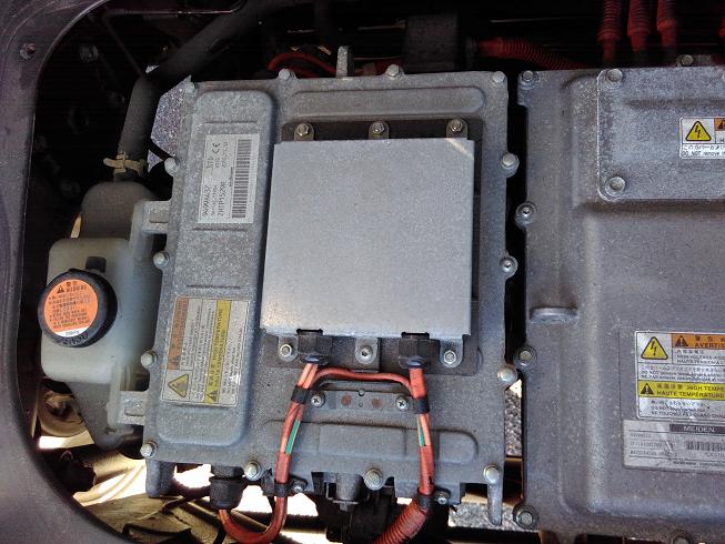
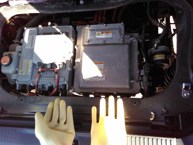
Is this the onboard charger you refer to?

wxTJA0c.jpg


So I get the limit of the charger is 4kW. Is anything else blocking for "dual" charging. I mean if putting in a second charger and making parallel wiring in to the MCU would this charge at 6,6/8kW?
Do you have any experience with this whether the car will charge at double rate, stay at 4kW or shut down?

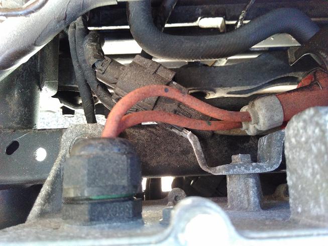
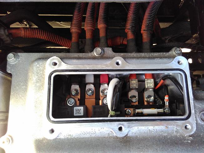
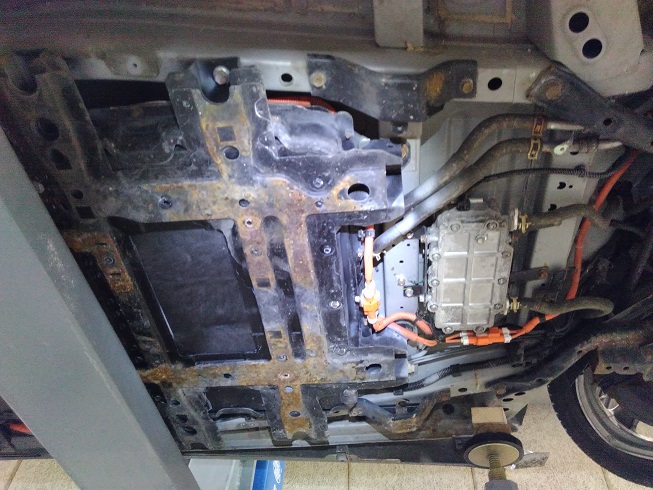
Is this where the wiring exits the charger?

mbfg8d7.jpg


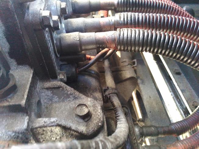
Charging wires entering MCU?

G3u45OM.jpg


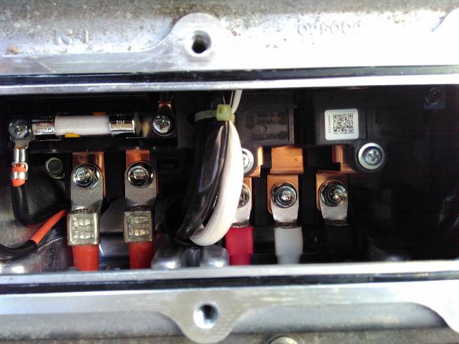
Inside MCU it looks as there is a 20A fuse. Can it be a fuse on the wiring from the charger?

9snK8F4.jpg


PV1 said:
This means that we can't parallel extra chargers to reduce charging time. But, what we can do is tap into the high voltage bus at the motor drive inverter (MCU) and feed in power from an external charger, a second battery pack, or both.

So this is where you suggest I connect the 2nd battery pack, on top of the two red wires on the right hand side?
ciXDSS8.jpg


PV1 said:
This requires the car to be READY. There is a small cover on top of the MCU that can be removed, allowing access to the terminals for both the motor and the HV cables from the battery.

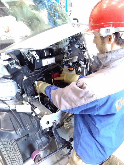
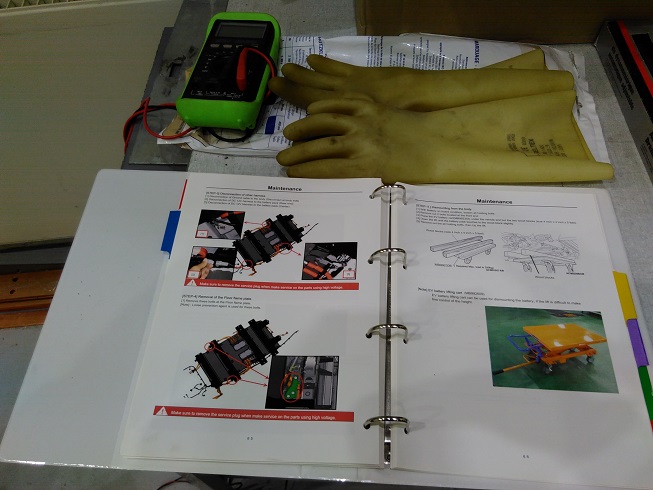
Just out of care for any one approaching this. Wear Protective Equipment this is high power stuff and will injure you if you short something which is live!

gVC0q4q.jpg


Just out of curiousity about the Quick Charge CHAdeMO which this car has. I was unable to locate the wiring.
Anyone knows where the onboard CHAdeMO receiver/controller is located on the car?
Any chance connecting a 2nd pack to this as alternative option to in MCU.
Maybe you already mentioned somewhere..

So it looks I am getting a wrecked car with parts to play around with. Where will I find the contactor for the battery pack on the wrecked version?
Any idea whether I can export the bms from the wrecked car as well on the 2nd battery pack?

Thanks.
 
The CHAdeMO has its own wires that run straight to the battery pack. These run down the inner fender on the left-hand side of the car and into the left side of the pack. Siai47 has successfully activated the contactors inside the pack to make the port live. But, he substituted the CHAdeMO port for an Anderson connector. This is how he connected a second pack to the car (connected an Anderson port to the quick charge terminals on the battery pack and manually powered the contactors inside the pack). There is a connector under the rear seat by the EV-ECU which has the leads for the QC contactors.

Yes, that is the on-board charger (and also the DC-DC Converter). Unfortunately, an external charger cannot be used with the on-board charger simultaneously, the car will shut down with an over-current error. But, by having the car in READY, an external charger can be used on its own by tapping the HV bus, either in the MCU or by hi-jacking the quick charge circuit. Yes, those two cables on the right hand side of the MCU is where the battery connects. This is where the HV bus can be tapped. This is probably the preferred spot as it leaves the CHAdeMO port available for use. It also allows for easier connection to a second pack inside the car (please observe proper care when dealing with high voltage, and especially with high voltage battery packs, which can be live at all times and provide un-fused current).

All contactors are located inside the battery pack.

This is where someone who's actually messed with the car takes over. ;)
 
As preparation for receiving a wrecked version of this car tomorrow I am trying to prepare by gathering informations around how to take off the batterypack from the car.

I was viewing Martin's video on youtube. And it was useful. However things are going very quick.

Anybody with a step by step instruction or link to a guide. I think I saw one posted somewhere in one of the threads. Any who can make a link to where it is?

Any practical experiences as of what to put the batterypack on to be able to access the bolts?

I've got access to a old mechanical forklift to put the battery on and a car-lift to lift up the car.

Thanks.
 
Dani, congrats and thanks for taking on this project and posting what you find!
Ben Nelson posted good videos of his dissection of a flooded i-MiEV
http://300mpg.org/2013/02/20/working-on-the-flooded-i-miev/
 
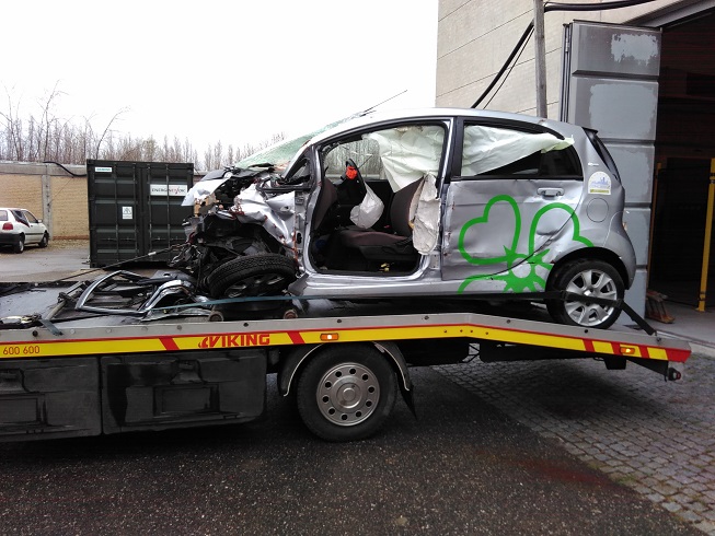
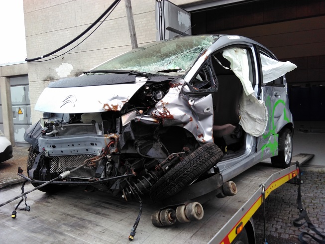
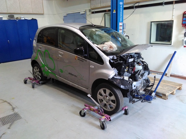
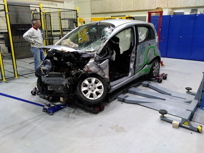
So the wreck has arrived.

CraNlH8.jpg


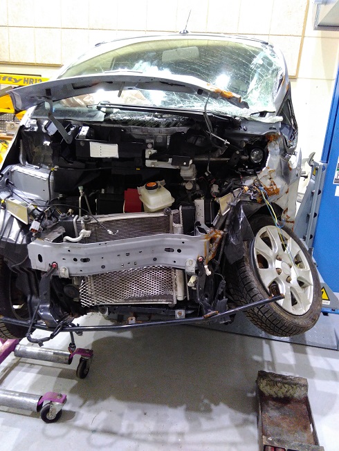
The front left wheel is pretty broke which means challenges getting the ev around.

es5ekov.jpg


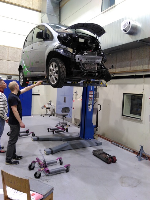
With help from the guy delivering the ev and a person from the local ev community we got the car in side and close to a car lift.

The car is now at a university where our local ev community has access to and within barely an hour of arrival we had several teachers/professors coming to follow the adventure.
Some of them very keen on telling us all the things we didnt do right and we couldnt do and then left, others fortunately gave us a hand pushing the car up on the car lift which is a one-sided version, sadly, as this will be challenging if not impossible to get the batterypack off using this one.

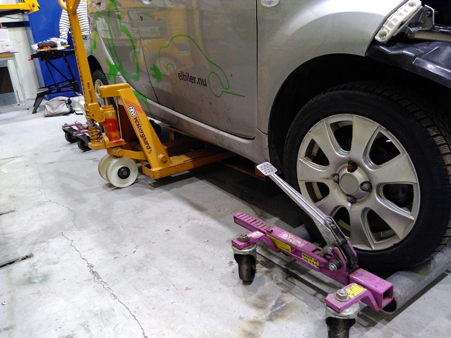
Later in the day, after work, I found a place to borrow some kind of rollers from a towing company to get the ev straighted on the lift.

AWQtJvK.jpg


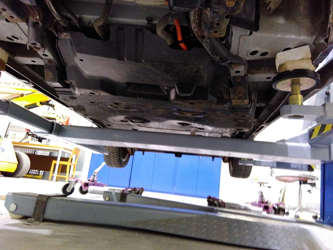
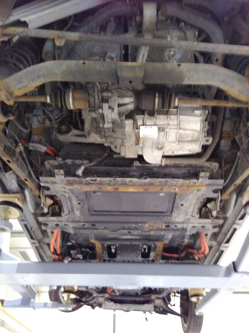
As trying to adjust the arms and extensions on the lift we discovered how much the batterypack actually stick below. I noticed this because this particular lift has a center base (which is right below the pack) from where the two arms to the opposite side sticks out.
So this took that we needed to add height on the arms to which I cut some pieces of wood and stacked up.
As being surrounded by academic engineers they had lots of comments as to how to place the wood to ensure most strenght and avoid the wood pieces from splitting up. As being rather exhausted hearing things I couldnt/shouldnt do I found myself saying to the 4 academic engineers "damn engineers..!". I see their point. Its just.. Longing for progress after a day of challenges and days of delays.


UujcoJk.jpg


As the ev finally was lifted up we discovered how the lift actually had a broken release handle, which is needed to lower the car down again. The lift was installed couple of days before so this came as a huge surprise. Of course we discovered this when needing to take the car down. F...!
Apparently a pin holding the release handle on the lift had broken. We found a screw to put in its place and made it work and notified the staff which was actually around following this progress Friday night at 18h. :) Nice!
Great with some backing up and support as well as interest from professors. However home was pretty pissed as time passed and showing up much later than agreed.

Here are some more pics from the ev:

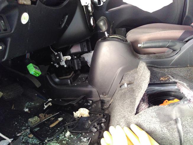
I got the hood opened up with some struggle.
We checked the circuit for any shorts by measuring the resistance between + and -. We checked the fuses if any of the main ones had blown. All seamed ok.
Then we measured the 12V batt. and this showed 0V. One of the professors found a new 12V 35Ah in one of the offices of another professor which we tried. However this batt. was apparently also low barely 8V without load and it dropped down to 5V when we connected this to the circuit. When we connected the new battery for testing the instrument panel showed "door open" light. Which indicates the circuit seams to work at least to some degree.
We got permission to leave the car indoors for the 12V battery to recharge from an external battery charger.
University rules are otherwise how all cars need be outdoor by the end of the day.
So we need to get the car out side by Sunday night and hopefully reach further by then. However its weekend and family time so.. we'll see.
Honestly I had hoped the battery had been off by now. Unexpected challenges regarding lift issues, new to this process and shape of the lift makes this more challenging.

PwJOHtG.jpg


dG1JTVs.jpg


As you can see the main switch is disconnected and tied to the steering wheel.

Any clue as to whether its safe and wise to re-connect the switch when trying to check Canion and EvBatMon, as 12V battery is charged and re-connected?

Do share input of experiences and know-how on what could help the process as to where this process is right now.
I might be too busy to respond in the next weeks time due to work and apointments.

Thanks!
 
I'd really like to have such a wreck at my disposal as well... Perhaps this should be moved to it's own topic though? Any admin see this?
 
So I reconnected the HV switch/plug

wYiUgbH.jpg


And connect a functional 12V battery.

cKk6HgG.jpg


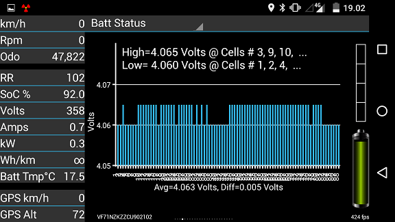
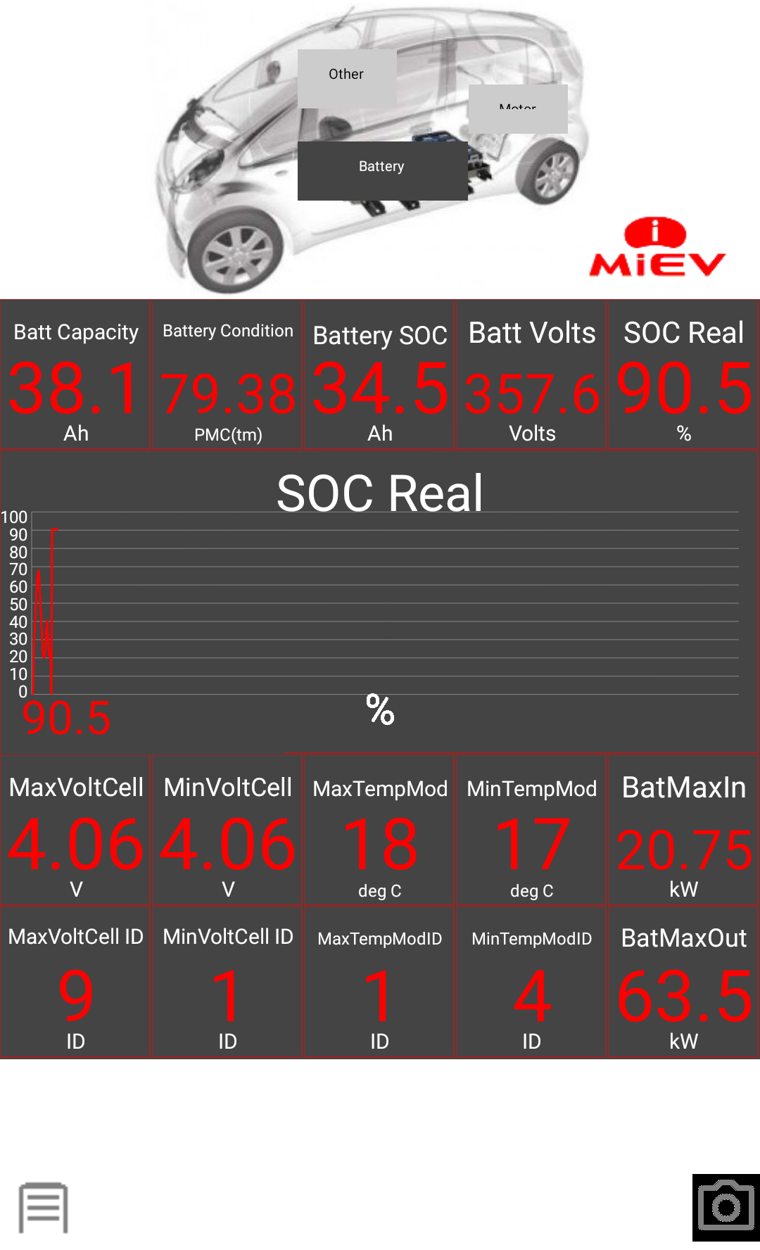
Data from the battery recovered using Canion

HANKYiC.png


The cell status from Canion (Thanks PV1!)

kmv7Pfl.png


Quite a relief to see the electrical system still working and able to provide these data

.. and data recovered using EvBatMon

K71tt8n.png


Interestingly the ev has driven barely 48.000km and its remaining capacity is still 79% which is about the same as our fully functional ev, same model and age which has only driven 10.000km and having 80% remaining.
 
OMG,

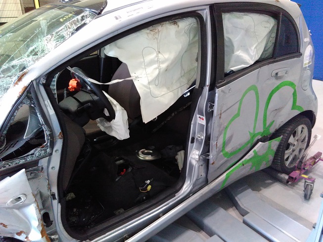
Its hard to believe that a car in this state is showing a ready light. With all the airbags deployed?

Did someone previously connect a mut 3 and clear out the accident codes ?

In any case i'm glad its in good electrical shape.

Dani what is the end game for this car ? Use the pack for the other car ? Just wondering. I would also like to have a wrecked one to play with.

Great pictures please keep us informed.

Don......
 
I think I found all the posts relating to this topic and moved them into this new thread and, for now, placed it into this subforum. All in the interest of being able to stay on-topic and find things in the future.
 
Wow, nice, 92% charge. You got lucky that the pack is so full. Also means it's intact since if there was damage surely the SOC would have dropped and/or you would have cells at a lower voltage.
 
So we made it by today.

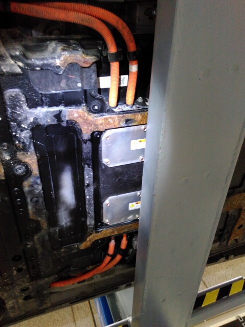
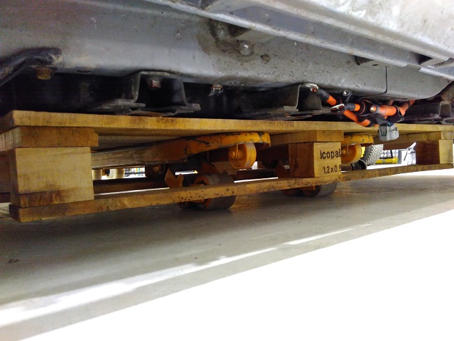
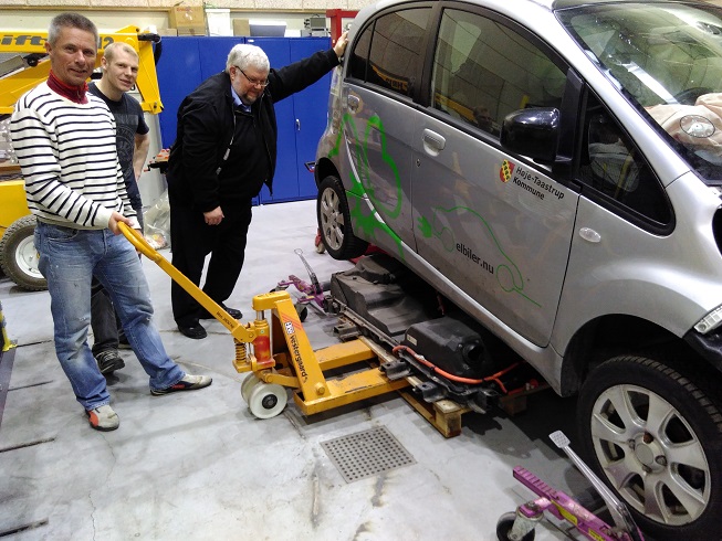
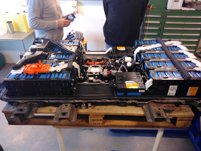
Disconnected the HV plug. Studied the manual. Took off the covers.. The metal coveres. Measured the Voltage. Disconnected the HV wiring. Disconnected plugs around. Took out 4 bolts holding the battery and loosened the rest. Put the car down. Pushed it off the one-sided-lift and over on a pallet. Lifted the pallet up under the battery pack and aligned the pallet with access to the remaining bolts. Unscrewed the remaining bolts. Lowered the pallet with battery on. Lifted the car further up in the air using a jack and another fork lift. Pulled out the pallet with batterypack.
Risky procedure lifting up the care like this. However this was a way we had access to as our car-lift is one-sided and unable to get the battery pack off using the lift due to center base lifting up under the battery.

See pictures below.

Reading manual and preparing equipment and personell.

IGdwDJc.jpg


Raising ev to remove cover.

XQ1rDib.jpg


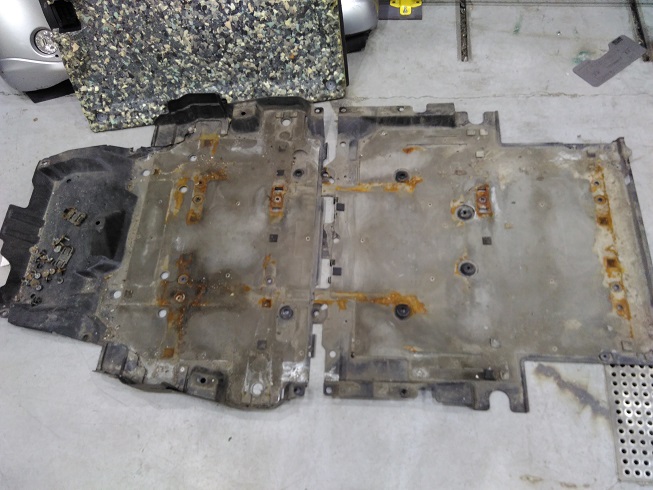
Cover off

XFAxSM9.jpg


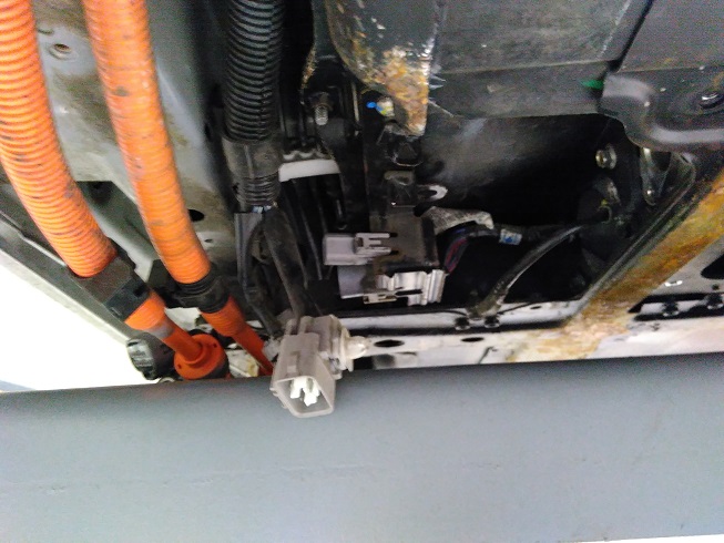
Disconnecting HV wires and other connectors to the battery

cMhIFOD.jpg


EjlOXGW.jpg


DDdLUDS.jpg


o3clrjY.jpg


4 Bolts removed and others loosened. The car lowered down and pushed away from the lift to do the complete unscrewing with battery resting on pallet. These wheel-rollers or what they are called were great help to manouver the car around. Great we could borrow them from a local towing company who had a pile of them at their workshop.

sfLMcal.jpg


hXdcAja.jpg


Battery supported by pallet. Now car gets raised using manual forklift in the back with wood pieces on to get the propper support.
And lifted from the front with a jack, rather use a second forklift if you can due to balance.

6a2vqdQ.jpg


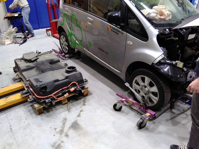
Voila! A little bit of tipping and we got the battery pack out on the pallet with help of some very nice ev community fellows.

K0f5uRY.jpg


And here it is. Ready to take a close look at another time.
We took it away and put the car out side as agreed with the university. Wonderful this was possible and thanks to all who help with info, equipment and workforce.

sUqLVfa.jpg


May this will be of contribution seeing and reading.
 
Dani I loved your description of the 'academic engineers'. Reminds me of when I dropped out of engineering school as an actual maker of things who lost patience with the theoreticians who were pretending to teach us.....
 
DonDakin said:
OMG,
Did someone previously connect a mut 3 and clear out the accident codes ?

In any case i'm glad its in good electrical shape.

..what is the end game for this car ? Use the pack for the other car ? Just wondering. I would also like to have a wrecked one to play with.

I'm unaware of any codes cleared on the ev before I got it.

The remaining parts of the ev is for spareparts and upgrades I think. Restoring is off the table for me at least.

As the initial intend was to get more range on our fully functional ev (same model) I'm considering to use the batterypack as range-extender. Fit it in the back, with seats down as I read somebody mentioned is possible. I wonder if this is also possible in the smaller version which we got which is 2011 european model?

In time perhaps make some kind of mobile version in chunks (12 pieces same way as they are lying inside the batterypack) and light enough to remove by hand after disconnecting.

Thanks for sharing your responses. Its always interesting to know how the sharing is received and what this bring others.

Another distant idea is to refurbish the recovered pack with 18650 cells with 3400-3500mA. However as this has been expressed in various threads this has some expense to it. 4€ a piece is the latest price I got from a local supplier when buying some 2100pcs and delivery time of 14weeks.
Such budget is out of the question at this point.
 
Dani - I seem to recall Siai47 had done this, adding an extra pack, and he thought the weight of the 2nd pack resulted in very poor handling. Do you need the extended range on a regular basis ? if not, you could consider putting the 2nd pack on a trailer ?
 
Yeah thanks for reminding. I am aware of the extra weight.
I've been considering designs for balancing the load and getting the weight close to the floor of the car.

I'm wanting to make a permanent wiring install of connectors so I still have the option to take out the additional cells when needed.

So far designs goes from being put around the rear footwells and then stacked up over the rear seats (removing the seats). To the option of putting some 4 of the lev50-8 on the front right footwell which puts some +60kg up front and leaves the remaining +105kg distributed around the rear footwells. In theory this would make the weight similar to driving around with 3 additional people weighing some 65kg each.
These setups of course makes the car 1 or 2 seater.
We mostly use this car this way and since I've gotten a bit of attention and support from a university then perhaps showing the possibility of a functional onboard range extender working in practice this might perhaps provide interest in financially supporting an upgrading to the stock battery with new cells. Or interest from others to make it happen.
Initial designs show how using 18650 cells of 3350Ah cells these could be fitted in a same way as existing lev50-8 and provide 43,3kW. Writting with Siai47 he argues how fitting packs from a wrecked tesla 85-90 would provide cheap cells and how some 75kW of cells could fit in of these cell-packs on the stock battery frame. This would require a new BMS of course.
Possibilities..
I checked for wrecked teslas by calling insurance companies asking for "totally damaged" tesla's which is a label used around here (Denmark) for cars which doesnt pay off to repair.
They had one in limbo meaning on the edge of payable, however when calling the repairshop which was doing the work on it they explained how all batteries are to be returned to tesla motors before they get new parts and the whole car/wreck was probably $70.000. New tesla 85 around here is around $120.000. So lots of financial space for the insurance to repair the car.
 
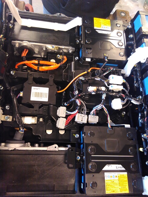
So we got the cover off

ZkxTgTt.jpg


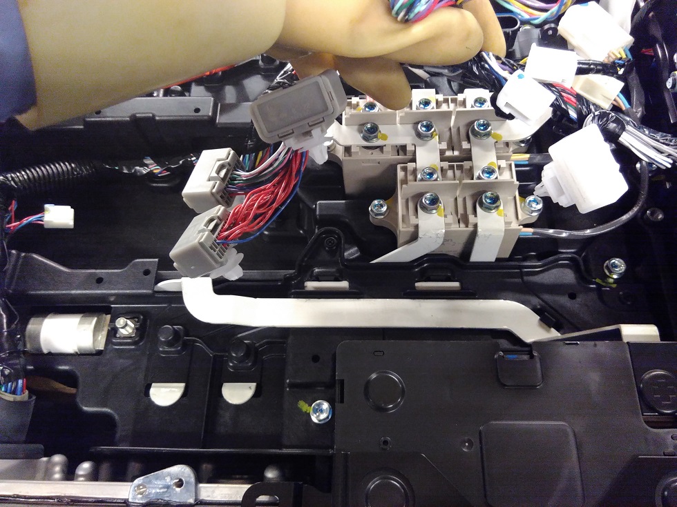
We tried to locate the contactor which I figured would be at the center below a whole lot of clamps. Tuff to get those off in the small space while using protective rubber glove.

NsdsZxo.jpg


After a while with rubber gloves on and an isulated flat screw driver I got the clamps off and I could remove the plastic cover.

XZocOHB.jpg


4hcGpRp.jpg


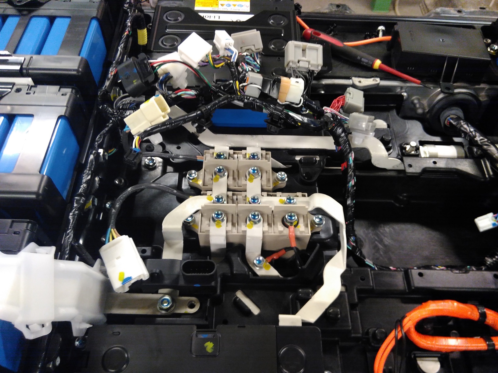
So there are two contactors. The front of the ev is to the right on this picture.
This ev has Chademo and those are connected at the top-right of the picture. Which brings me to think the top contactor being the Quick Charge contactor. Anybody who can verify this from experience?

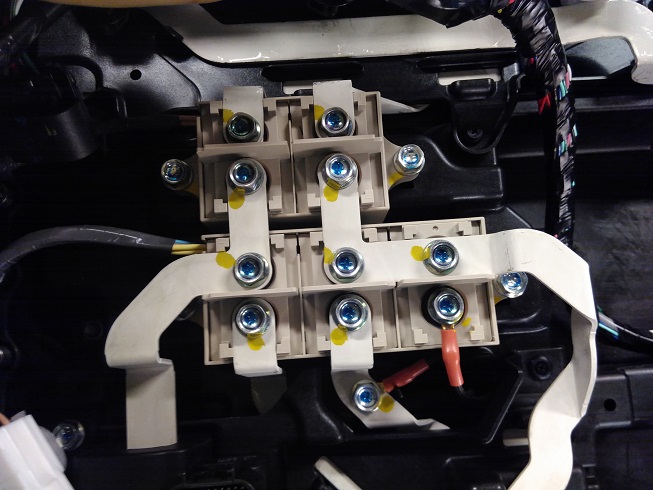
The bottom one seams to connect the battery cells on the top three terminals, and the bottom two I'm guess are going to the HV wiring terminals for the MCU. Again anybody who can clarify any of these assumptions?

xdOKqO7.jpg


This will be the contactors pictured from the other side while lifting up the connectors. Front of ev to the left on this picture.
The Chademo HV wires connect at the bottom of this picture on the back side of the frame.
To the left is a 250A fuse.

Anybody knows if the BMS has a modul located down here in the batterypack somewhere?

Careful when you play around down here. This pack has 357V DC on. I had to repeat this message several times to members of the community who kept putting their bare hands close to the naked metal conductors. I guess you call those buss bars.

Hope this contibutes with info or at least entertainment about the little project on going here.
Seams my action with this wrecked ev sparked some renewed interest in the ev community here which had turned in to a sit-down-coffe-club,
at least this is how one of the members explained it to me. Now they've got plans of getting another wrecked ev to work on.
 
This is great, thanks for posting the pictures--these are never-seen-before views of the contactors and buss bars.

Were the buss bars painted or coated with something--they appear white in the pictures and look like the surface has cracked in some of the bends?

Can you point out the positive and negative terminals on the contactors, maybe we can figure out the routing and cell numbering used in the pack?

In the third picture of the previous post there is a contactor with red terminal lugs going to the adjacent buss bar--i'm thinking this is the pre-charge resistor connection from the pre-charge contactor to the B+ feed from the pack. Could you measure the value of that resistor?

I'm going to make some guesses:
In the last picture of the previous post i'm going to guess that those are the chademo contactors and the positive terminal is on the left--so the wires from the dcqc port will cross on their way to the pack since the chademo dcqc connector has the positive pin on the right looking into the connector.

Also that the most negative cell in the pack (CanIon cell #8) is located in the 8-cell module in the far right corner in the back, and the most positive cell (CanIon #85) is on the interior terminal of the 4-cell module on the right side of the pack.

Also guessing that the main fuse is located between cell 52 in the front half, and cell 41 on the 4-cell module on the left side of the pack.

See my blog for this updated drawing of the cell numbering
pack_numbering-300x190.png
 
Back
Top