kiev
Well-known member
Just for grins, what are the pins?can bridge between the ev ECU and the BMU.
ECU connector and pins:
BMU connector and pins:
Just for grins, what are the pins?can bridge between the ev ECU and the BMU.
Just for grins, what are the pins?
ECU connector and pins:
BMU connector and pins:
Yes, first to admit I’m no expert but looking at the code you posted I gather that it reads data on Can1 and sends it to Can0, then reads Can1 but the corresponding send to Can0 is missing??It passes messages from the EV ECU to the BMU and from the BMU to the EV ECU if that is what you mean.
Well, good catch. I’ll have to look at it when I get home. Maybe I truncated it somehow by accident. It was supposed to be sending both ways. Rookie mistake. ThanksYes, first to admit I’m no expert but looking at the code you posted I gather that it reads data on Can1 and sends it to Can0, then reads Can1 but the corresponding send to Can0 is missing??
I was thinking along the same line.... maybe I'm not getting some command from the ECU to the BMU like extended packets or something and it is expecting a response.Maybe have to set some filters for just the PIDS for the BMU. The full buss traffic may overwhelm the bridge? except you wouldn't expect too much just during charging...so that is puzzling
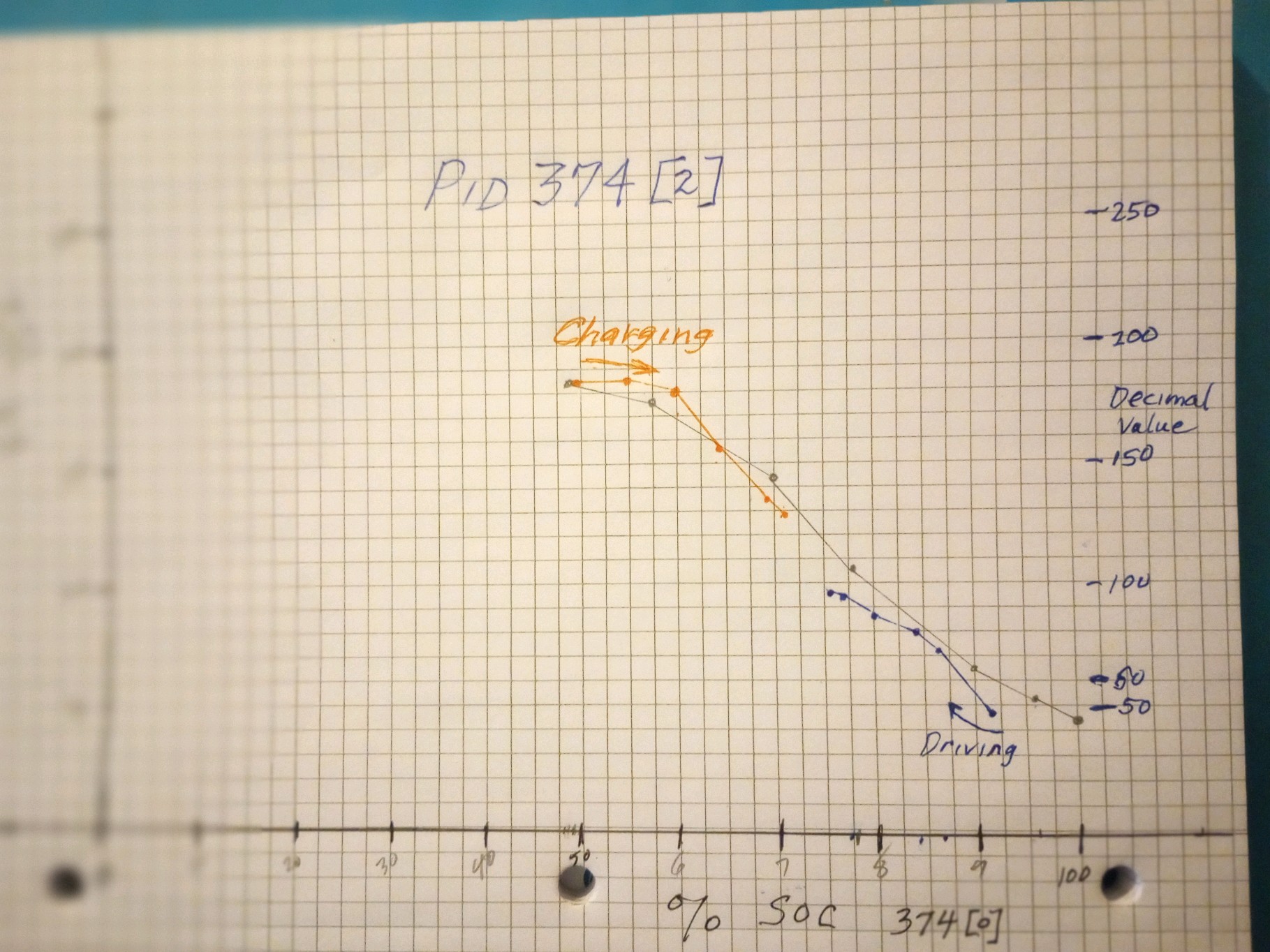
If I understand you correctly byte 6 is the max battery capacity @100% SOC (roughly 45Ah with a new battery) did you multiply this value by 2 and send it to the ECU (which has a 60Ah limit)?I played around with modifications. When I modified 374 byte 6, the estimated range value on the dash changed. Note that byte 6 is static. It never changes and OBDZero says it’s the capacity of the battery as reported by the BMU. So I multiply byte 6 and send it to the ECU. My range went to 131 miles. I changed nothing else. The car went to ready and I drove 7 miles, then I got the dreaded car ! Error. Still drove normally, so I came home. The MUT reported can bus errors indicating it lost communication with the BMS and meter. Seems like the ECU is looking at these other values in PiDs 373 and 374 for vehicle health. Now, to play around and see what the others affect.
I’m adding SoC calculations based on 90Ah and then I’ll take another drive.
No byte 6 isn't constant. It is one of two numbers on the network that give the present battery capacity. The other is PID 762 byte 0 = 36 bytes 3 and 4. 374 Byte 6 has a resolution of 0.5 Ah while PID 762 has a resolution of 0.1 Ah. piev changed the RR when he changed the value of 374 Byte 6 so we know that 374 byte 6 is the capacity used to compute the RR. In my experience 374 byte 6 varies more than 762 capacity.If I understand you correctly byte 6 is the max battery capacity @100% SOC (roughly 45Ah with a new battery) did you multiply this value by 2 and send it to the ECU (which has a 60Ah limit)?
Sorry, you are correct but it doesn't change often. in my case it shouldn't matter for experimentation since I'm just multiplying it by 2. Based on my experiments the ECU is calculating Rest Range based on [0] and [6]. [1] seems to drive the display if my memory is correct.No byte 6 isn't constant. It is one of two numbers on the network that give the present battery capacity. The other is PID 762 byte 0 = 36 bytes 3 and 4. 374 Byte 6 has a resolution of 0.5 Ah while PID 762 has a resolution of 0.1 Ah. piev changed the RR when he changed the value of 374 Byte 6 so we know that 374 byte 6 is the capacity used to compute the RR. In my experience 374 byte 6 varies more than 762 capacity.
Which of these if either is the true capacity is a good question. In any event knowing the capacity more precisely than +-0.5 Ah is a challenge.
Great progressOk, update.
I wrote some code to calculate my own SOC. I was able to drive over 100 miles. My algorithm was not too good so it said I was empty around 3.5 volts. So, that means I should be able to go a good bit more before empty.
I haven't figured out the turtle yet.
piev said:I wrote some code to calculate my own SOC. I was able to drive over 100 miles. My algorithm was not too good so it said I was empty around 3.5 volts. So, that means I should be able to go a good bit more before empty.
Not convinced as some reported that they could turn on the tortoise or even shut down the car just by changing SOC? One early tester also mentioned that he was able to almost completely empty the cells (2.8V) without any sign of tortoise or power loss when he artificially increased the battery capacity and kept driving?I'm almost certain the the car's power down function is based on low cell voltage not SoC. In some of the data piev has sent the car is still running at full power even though SoC1 and SoC2 are zero. They are zero because they are based on the reset capacity of 45 Ah when the true capacity is 90 Ah. The BMU's Ah account is 0 because more than 45Ah have been used.
Yes, I believe you are correct. I am not finished characterizing the behavior. Yesterday, driving home the vehicle suddenly stopped. I sent you the data. Not sure why yet, I got no turtle I just lost all power and ready went off. it wouldn't start back up either. I plugged in my laptop and changed the SoC and it went to ready and I drove home. Still no turtle. So, I believe the turtles come on from low cell voltage. I haven't drained the battery enough for that to happen so I may just play with changing some cell voltages with the bridge to see what happens.Computing the SoC from the voltage is quick and easy solution and it is a step in the right direction. But it doesn't work well unless the amps are between -1 and 1 for at least some minutes. When the battery is under load the SoC computed from the voltage can be as much as 20 % points below the true SoC.
When the battery is under load or charging a more accurate SoC can be found by keeping an account of the Ah in the battery using coulomb counting. The SoC is then equal to 100 * remaining Ah / capacity Ah.
I'm almost certain the the car's power down function is based on low cell voltage not SoC. In some of the data piev has sent the car is still running at full power even though SoC1 and SoC2 are zero. They are zero because they are based on the reset capacity of 45 Ah when the true capacity is 90 Ah. The BMU's Ah account is 0 because more than 45Ah have been used. However the cell voltages are still well above the power down voltage.
piev said:I plugged in my laptop and changed the SoC and it went to ready and I drove home.
Enter your email address to join: