Main Traction Battery Upgrade i-MiEV

Mitsubishi i-MiEV Forum

Help Support Mitsubishi i-MiEV Forum:

This site may earn a commission from merchant affiliate links, including eBay, Amazon, and others.

piev

Well-known member
Joined
Jun 12, 2018
Messages
77
First of all, there are many threads already here about this type of endeavor.
I was asked to start a thread on my project. I must say I couldn't have gotten this far without all the great posts on this and other forums.

I have had a few setbacks but won't bore you with the details.

Current state of the project:
New battery cells 93Ah NMC are installed in the vehicle.
Range was reset with MUT3 SE using windows driver by kolyandex to 45 Ah.
Current range 66 miles.

I accomplished this last year but then got in an accident and had to find a new car to finish this project.
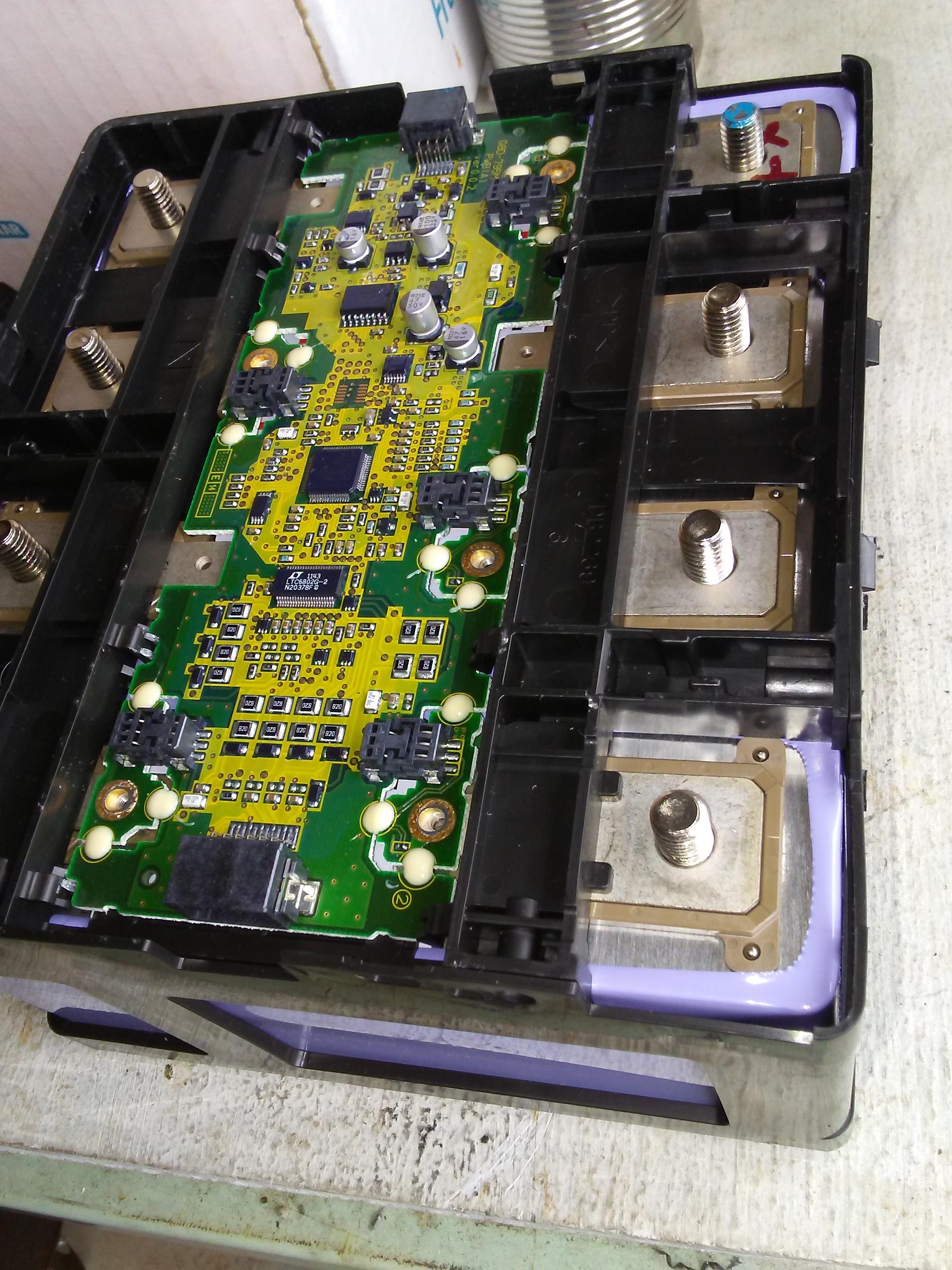
When I moved the battery pack to the new vehicle I had a bad temperature sensor on one CMU board and the vehicle would not go over 35 mph or charge.
So, I put a CAN bridge between the CMU and the BMU to fake the data for that one sensor.
I was able to charge the battery to full and it drove normally.

Hardware:
I used an Arduino Due with a Dual CAN Bridge made by Daniel Kasamis from ~bit TOGGLEBIT.
The Cells I used I bought from Alibaba. 93Ah 3.7V nominal charge to 4.2V
They also sell a 75Ah that will fit in the original space.
I paid around $70 a cell with shipping to the USA from China.

One thing I didn't notice was the size of the terminals. they were M6 and the LEV50 had M8's. The sales rep said they could change these but I already had the cells.

I will add posts as I think and decide what would be useful for people that want to do their own.
 

Attachments

  • IMG_3057.PNG
    IMG_3057.PNG
    111 KB · Views: 7
  • KSSS1050.JPG
    KSSS1050.JPG
    83.5 KB · Views: 7
New battery cells 93Ah NMC are installed in the vehicle.
Range was reset with MUT3 SE using windows driver by kolyandex to 45 Ah.
Current range 66 miles.
Great stuff, why set the capacity to 45Ah, if I remember correctly kolyandex advertised that he is able to hack the BMS and increase that value?
 
This is great news to get it working again after being hit and total your car.

And to bypass the bad thermistor value on a CMU,

Mitsubishi NTC thermistor:
TH05-3N682F is p/n for a 1% device
 
Great stuff, why set the capacity to 45Ah, if I remember correctly kolyandex advertised that he is able to hack the BMS and increase that value?
Kolyandex said he would increase the capacity and then he quit responding to messages.
 
I pretty much used one of the example in the dueCAN library.

I think I changed the Baud rate for CAN messages to 500kbps and removed the console logging print statements because it was causing bus errors too slow I suppose. maybe using interrupts would work better if that is desired.
I am sure there are some sophisticated programmers here but it's not me. I tried to post this code in an insert like I see all the time but couldn't figure it out. If someone can point me to instructions that would be helpful and I'll edit this post.

// Arduino Due - Displays all traffic found on either canbus port
// By Thibaut Viard/Wilfredo Molina/Collin Kidder 2013-2014
// Required libraries
#include "variant.h"
#include <due_can.h>
//Leave defined if you use native port, comment if using programming port
//This sketch could provide a lot of traffic so it might be best to use the native port
#define Serial SerialUSB
void setup()
{
Serial.begin(115200);

// Initialize CAN0 and CAN1, Set the proper baud rates here
Can0.begin(CAN_BPS_500K);
Can1.begin(CAN_BPS_500K);

//By default there are 7 mailboxes for each device that are RX boxes
//This sets each mailbox to have an open filter that will accept extended
//or standard frames
int filter;
//extended
for (filter = 0; filter < 3; filter++) {
Can0.setRXFilter(filter, 0, 0, true);
Can1.setRXFilter(filter, 0, 0, true);
}
//standard
for (int filter = 0; filter < 7; filter++) {
Can0.setRXFilter(filter, 0, 0, false);
Can1.setRXFilter(filter, 0, 0, false);
}

}
void loop(){
CAN_FRAME incoming;
if (Can0.available() > 0) {
Can0.read(incoming);
if (incoming.id == 0x653){
incoming.data.byte[2] = incoming.data.byte[1];

Can1.sendFrame(incoming);
}
Can1.sendFrame(incoming);
}
if (Can1.available() > 0) {
Can1.read(incoming);
}
}
 

Attachments

  • 20130428_143954_resized.jpg
    20130428_143954_resized.jpg
    151.7 KB · Views: 3
Kolyandex said he would increase the capacity and then he quit responding to messages.
That’s a pity as increasing the max capacity is the first step to unlock NMC cells, if you then map cell voltages from NMC to LEV50 you could essentially create a ‘LEV93’ pack…
 
I imagine that it is the BMU which manages the capacity of the battery. Isn't it possible to fool it by modifying the messages on the CAN bus?

Can you give us the name of the vendor on Alibaba ? How did you choose it ?
 
I imagine that it is the BMU which manages the capacity of the battery. Isn't it possible to fool it by modifying the messages on the CAN bus?

Can you give us the name of the vendor on Alibaba ? How did you choose it ?
I believe so. I haven’t finished my posts and will cover this soon.
 
General Electronics Technology (shenzhen) Co., Ltd.
Contact name:
Mitchell Huang
Registered company address:

CN,Guangdong,Shenzhen,4th Floor, Building 5, Mingkunda Industrial Park, Huachang Road, Langkou Community, Dalang Street
Company tel:
86-755-81762726621
Company email:
[email protected]

NCM Rechargeable Battery 3.7V 93Ah with M6 Screws

I think you can get M8 screws and use nuts off of the original cells.
I ordered 4 cells first and tested them. The specs all checked out so I ordered more.
 
There are some mechanical differences between the NEV50's and the new cells. The NEV50 cells have drilled and tapped holes to mount the BMS boards which the new batteries do not have. I made jumper wires with ring terminals that mount to the boards and the terminals.
 

Attachments

  • IMG_2879.JPG
    IMG_2879.JPG
    67.7 KB · Views: 10
  • lev50 dimensions.jpg
    lev50 dimensions.jpg
    105.7 KB · Views: 9
  • MNCJ1669.JPG
    MNCJ1669.JPG
    50.5 KB · Views: 11
The temperature sensors are located on the CMU boards, not on the LEV50 cells. But they are coupled to the cell terminal plates thru the M4 screw joints.

Since there is no real thermal control for the Pack (just blow some air around inside), it is a question of how effective or important are the temperature measurements?

Zoom in on lower right of the CMU in this photo to see a tiny surface mount resistor-looking thing between the 2 white blobs. There are M4 screws that mount the CMU to the cell pads, and the M8 studs for the link buss bars on the outer cell edges.

gdMza6t.jpg
 
Last edited:
Sorry, should have been more precise in my query, it appears the underside of the CMU (where the sensor is located above) is no longer mounted to the cells, therefore they essentially measure ambient temperature?
 
True enough. Big thermal time lag if you are needing to know actual cell temperatures.

But how are cell temperatures used?

If its too cold--don't allow charging.

If its too hot--turn on blower air.
Maybe limit Pack current while driving? Maybe don't allow READY mode?

If the signal is missing due to interrupted CAN buss? Then the car won't go to READY and the blower fan comes on full blast.

There are likely some Safety related actions based upon cell temperature.
 
Last edited:
I tried to post this code in an insert like I see all the time but couldn't figure it out. If someone can point me to instructions that would be helpful and I'll edit this post.
I think you want the code tool, it's an "extended" icon, so you have to get to it via a three-dots icon:

1708657028159.png
First highlight by dragging the cursor over all the code you want formatted, then click the code icon.
 
Last edited:
Found my issue with the thermistor.
For some reason that I don't remember now I put a washer on this one CMU connection.

Thanks to Kiev, he spotted it immediately. Apparently, the washer was on top of the trace and had shorted the thermistor.
Resistance was 0.6 Ohms. I removed the washer and it went up to 12K Ohms.

Put the car back together and it charged fine and drove normally without my Bridge device.
 

Attachments

  • Bad Thermistor(1).jpg
    Bad Thermistor(1).jpg
    74.3 KB · Views: 10
  • Bad Thermistor.jpg
    Bad Thermistor.jpg
    62.3 KB · Views: 8
Hey All,

A little update for you.

I did a range test today.

I drove 8 miles after the turtle came on down to 0.3Ah at which point my power dropped significantly and then at 0.1Ah the car stopped and wouldn’t go any further.

I was reading these values with OBDZero. The car just said …. For remaining range and I used the trip counter to keep up with distances.
 
It means that the remaining range meter displayed … and I kept driving. The turtle light came on and I drove 8 more miles with no miles left on the gauge and the turtle light on.

It also means that no matter what voltage the cells are at the car will stop when the remaining capacity goes to 0.1Ah.
 
Last edited:
Back
Top