Search for a used OBC from a salvage yard--there are lots of wrecks out there and they want to sell the parts. i have bought several OBCs that way in the $300 to $500 range. Also aebay.
Last edited:


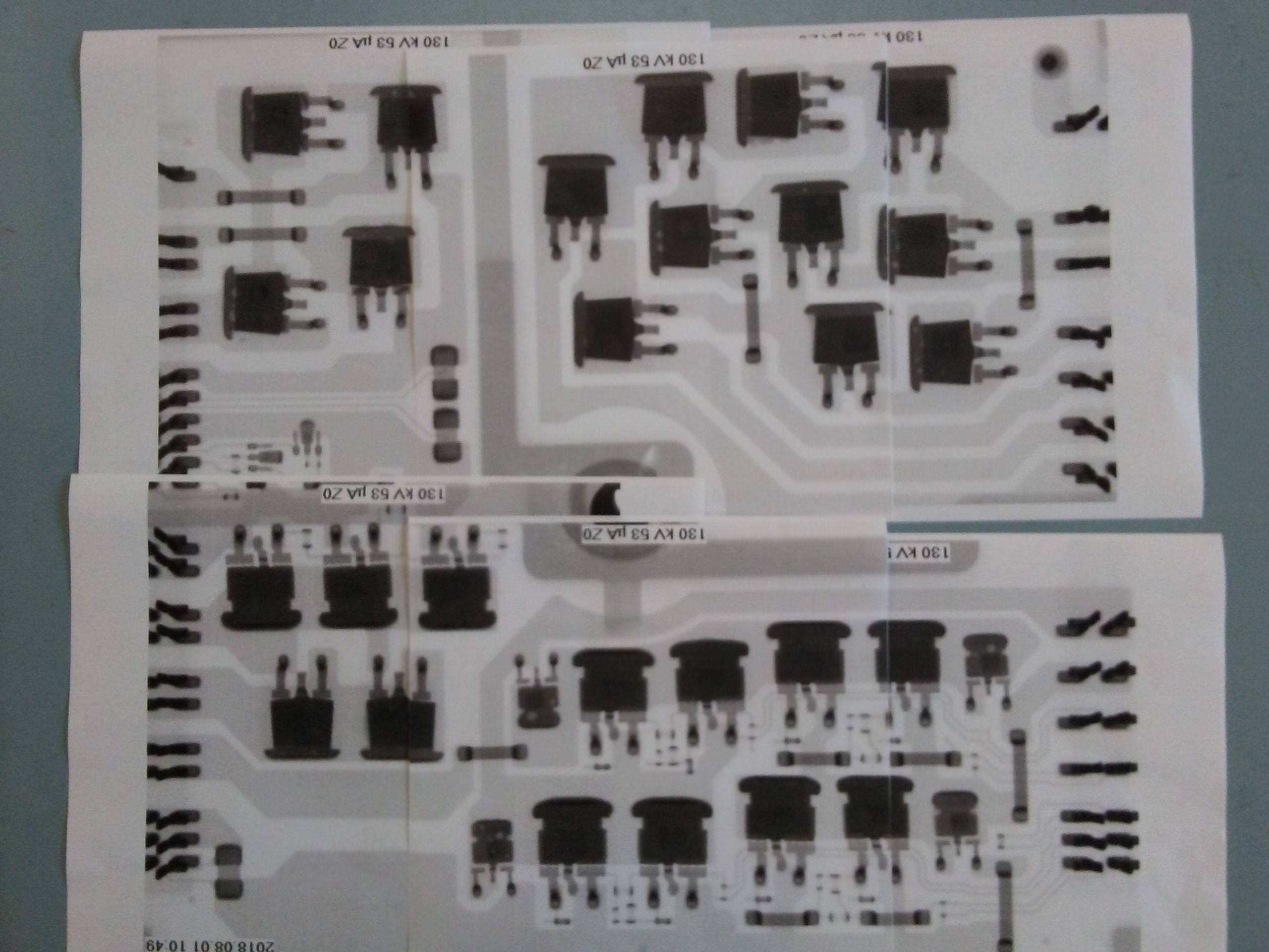
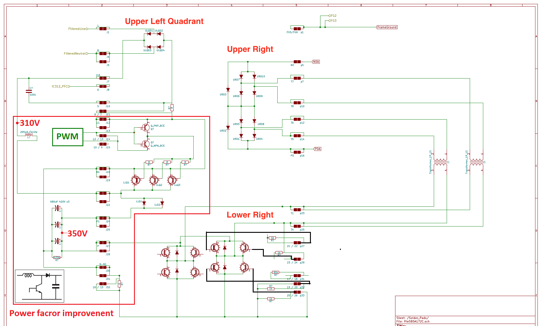
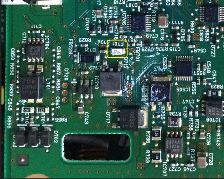
I see there are several user OBC units in Norway for around 800$ but that would probably cost a fortune to send to US (I guess you are located there)Hello all you great members of this amazing forum. On my saga to repair my i-Miev, last I left was that the waffle plate H Bridge IGBTs are bad, some shorted, some open. Tried several things to remove the epoxy, and with no replacement used charger in sight, plus no decent offers with the car on that condition, I decided to make the H-Bridge on a separate PCB outside of the waffle plate. Waiting on this half bridge IC STGSH80HB65DAG. While waiting, I would like to know if someone has scoped the gate voltage (pins 25 and 26). I mainly want to know the shown peak to peak voltage, since the device is not the same and there are no specifications for the RJP6012 anywhere and I want to ensure there is no magic smoke with the replacement. I'm still looking for a known good waffle plate to avoid the modification. Thanks!


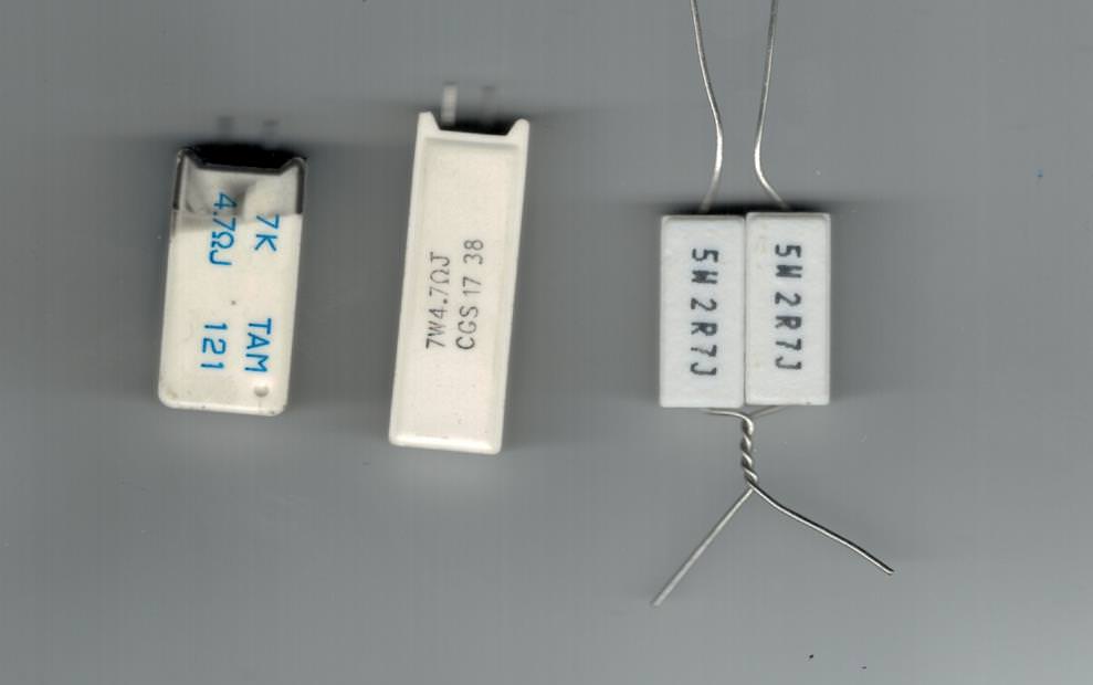
Or just one 16 A thermal fuse. The P10K resistors have a single 15 A rated thermal fuse in them:Hmmm. I may be veering into hillbilly country here (and crowding the little real estate there is to deal with), but how about functionally replacing the P10K resistor with your pair of paralleled 10 Ω Ohmite resistors in series with a parallel pair of the AuPo 16 A thermal fuses I found?

Thanks Piki. I found one in Japan, but $920 in shipping was rather unappealing. Where did you see this, Ebay?I see there are several user OBC units in Norway for around 800$ but that would probably cost a fortune to send to US (I guess you are located there)
https://finndel.no/bildeler.aspx?dk=0233&bk=3728&srt=0Thanks Piki. I found one in Japan, but $920 in shipping was rather unappealing. Where did you see this, Ebay?
Thanks Piki for the quick reply. I'll take a look

Can you provide a link please? I can't find it.Ebay:
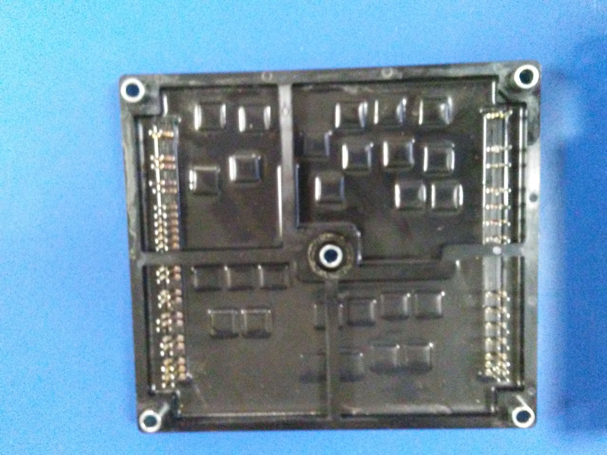
CZ1525-RPWR-012 Hybrid IC (Waffle Blade)
Me neither... Hopefully they will not be gone when I get to see itCan you provide a link please? I can't find it.
I wonder where they are getting these from. Perhaps a parts seller went out of business?
Update:OK, so the old battery was not the issue. How do I modify the old post, cannot find that function on the forum?
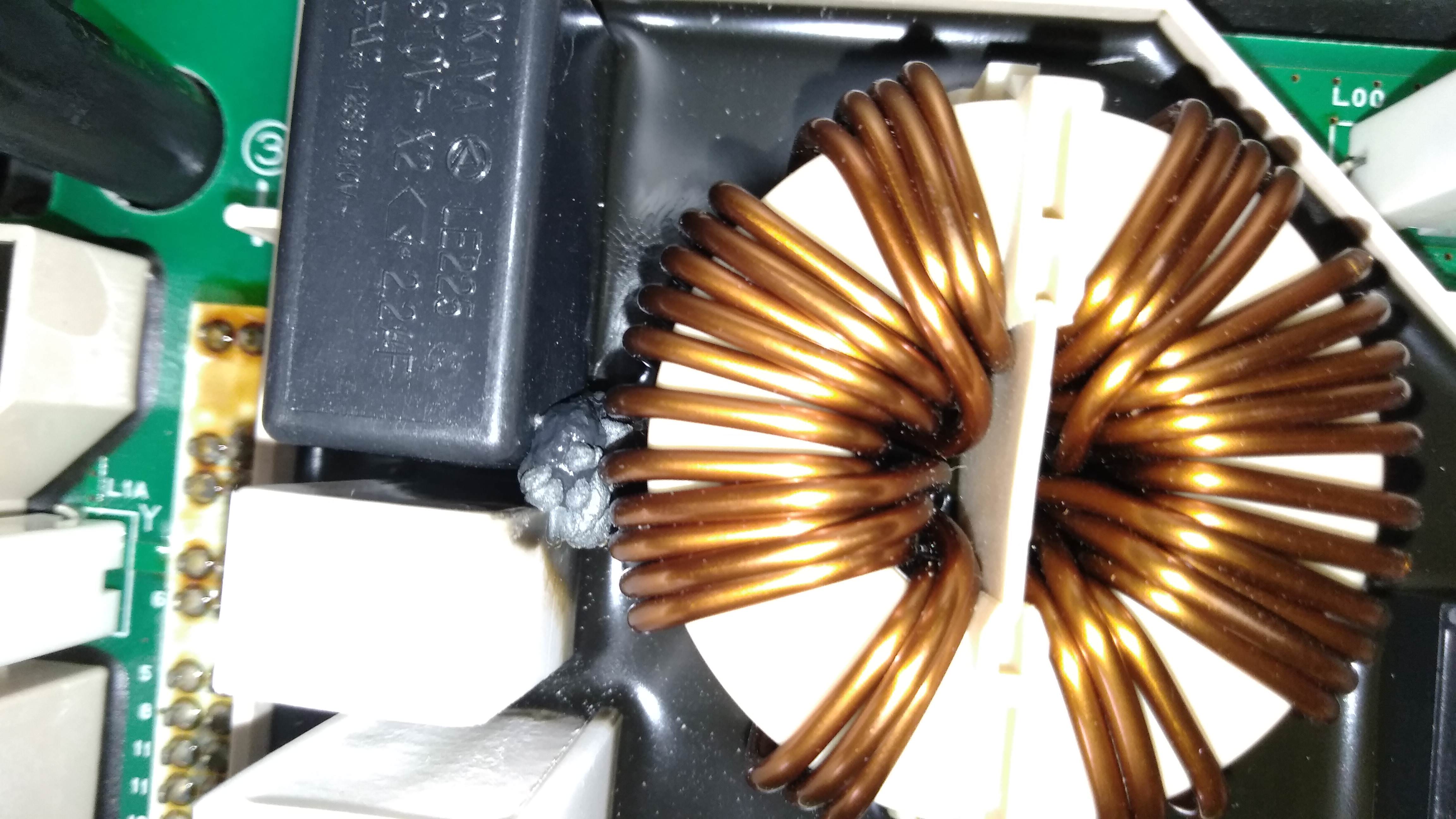
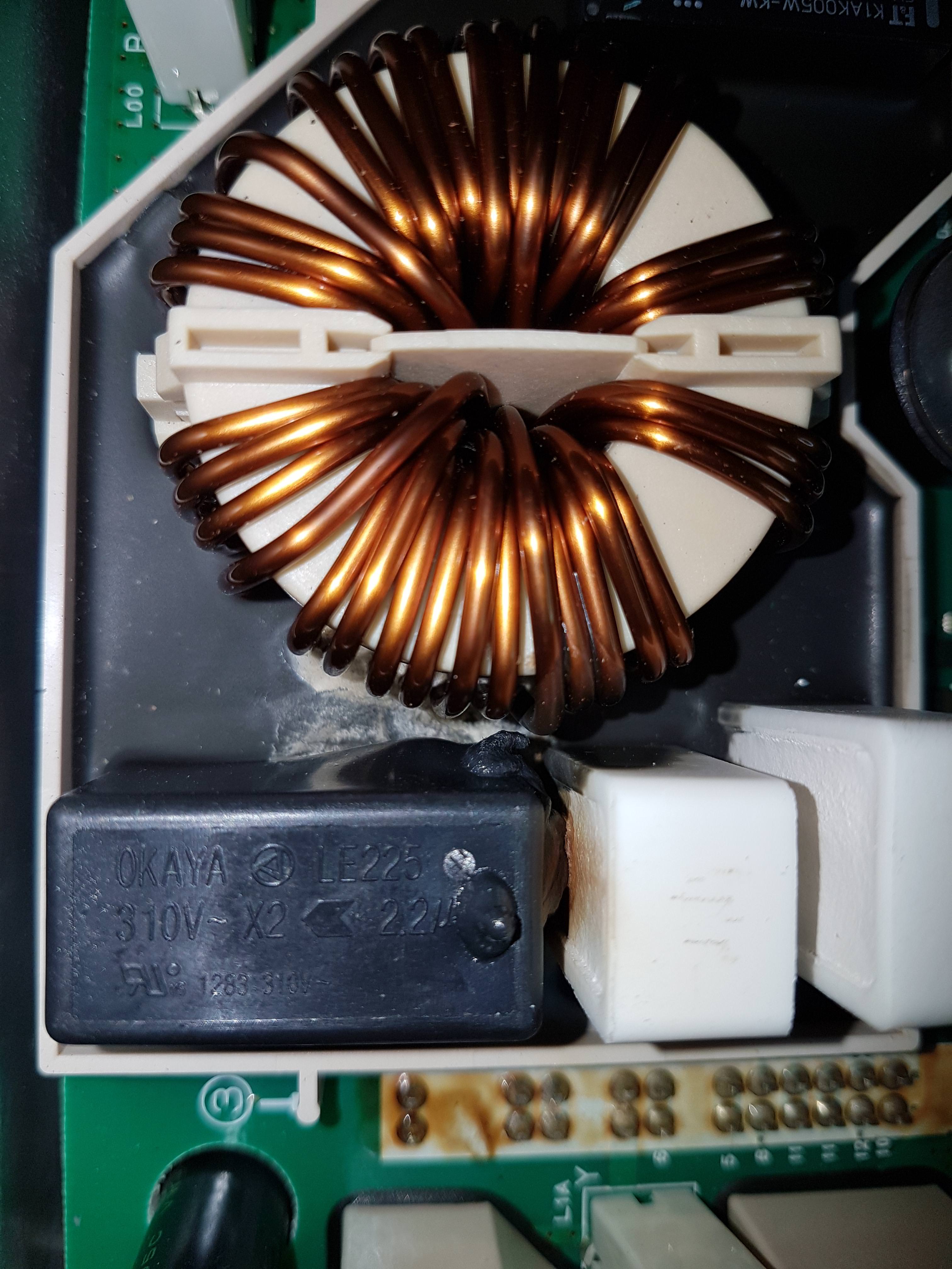
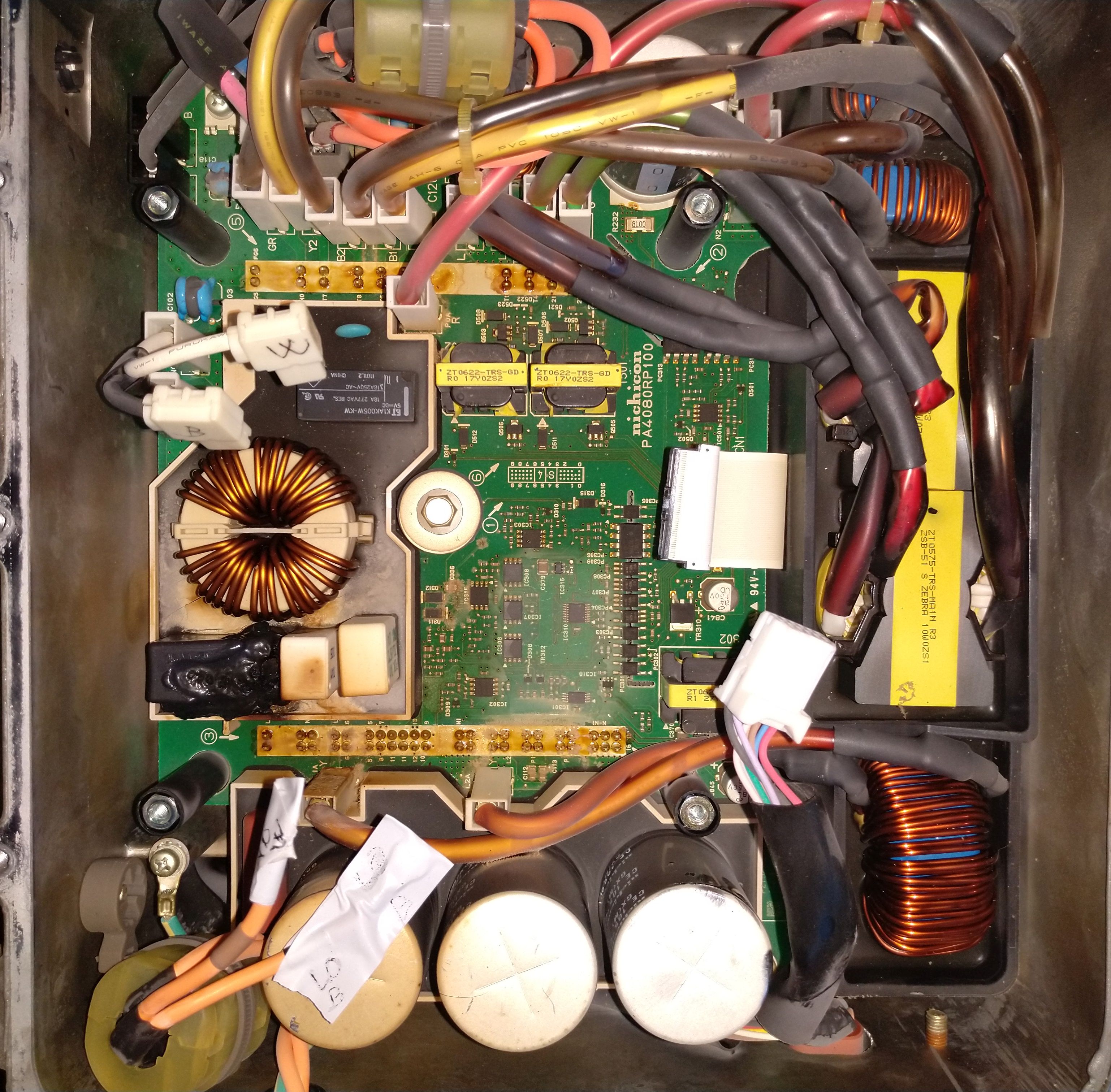
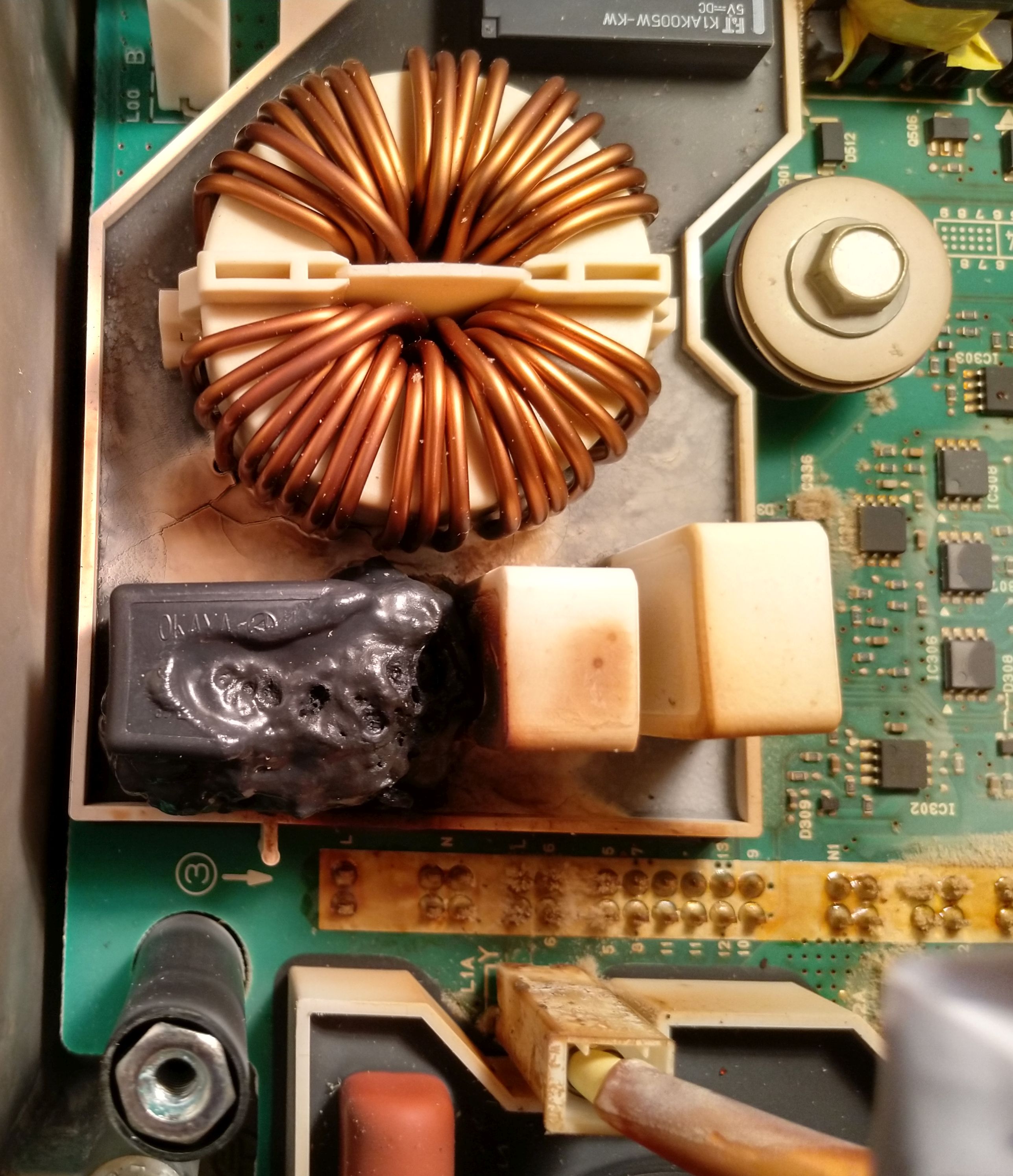
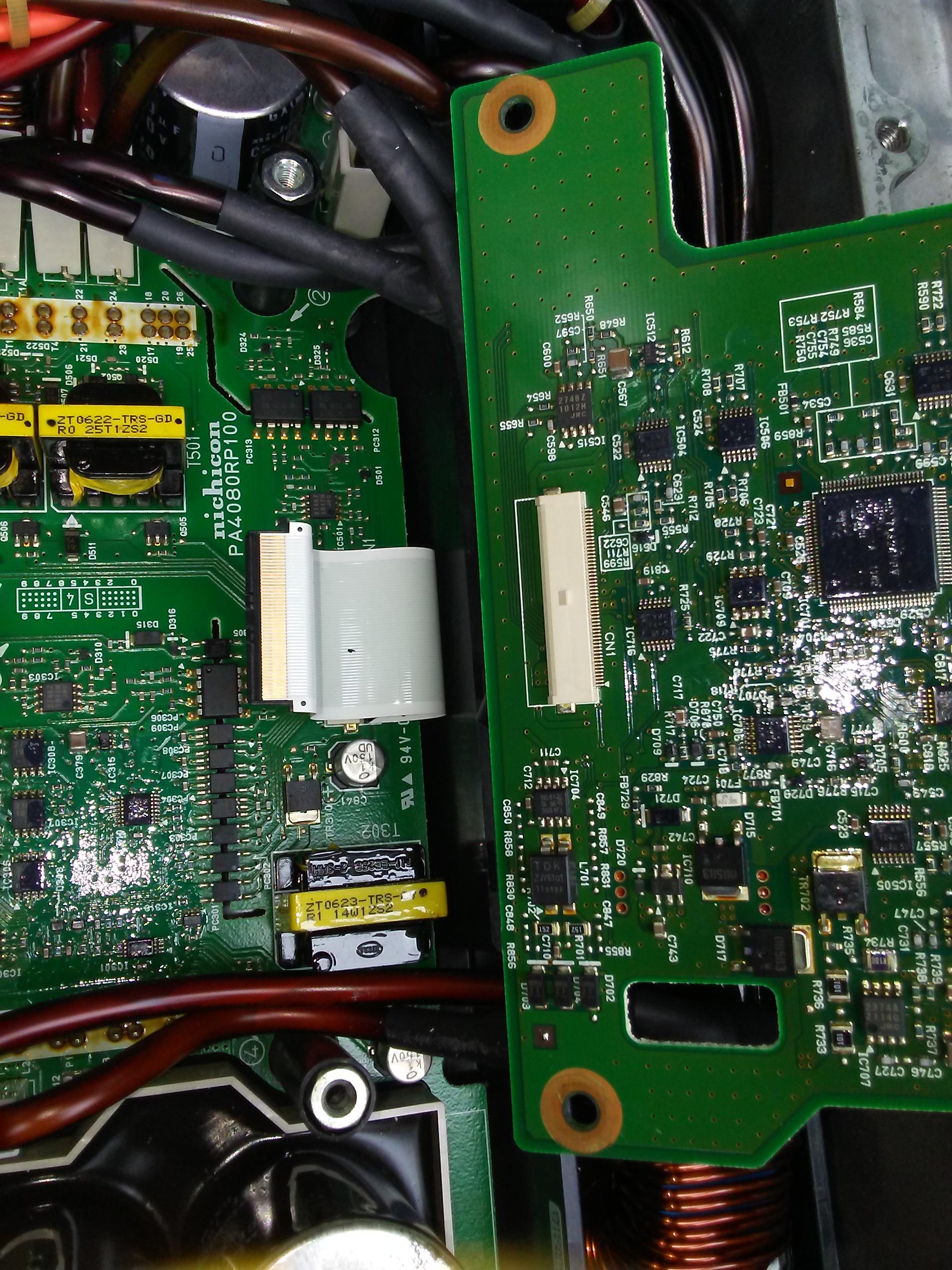
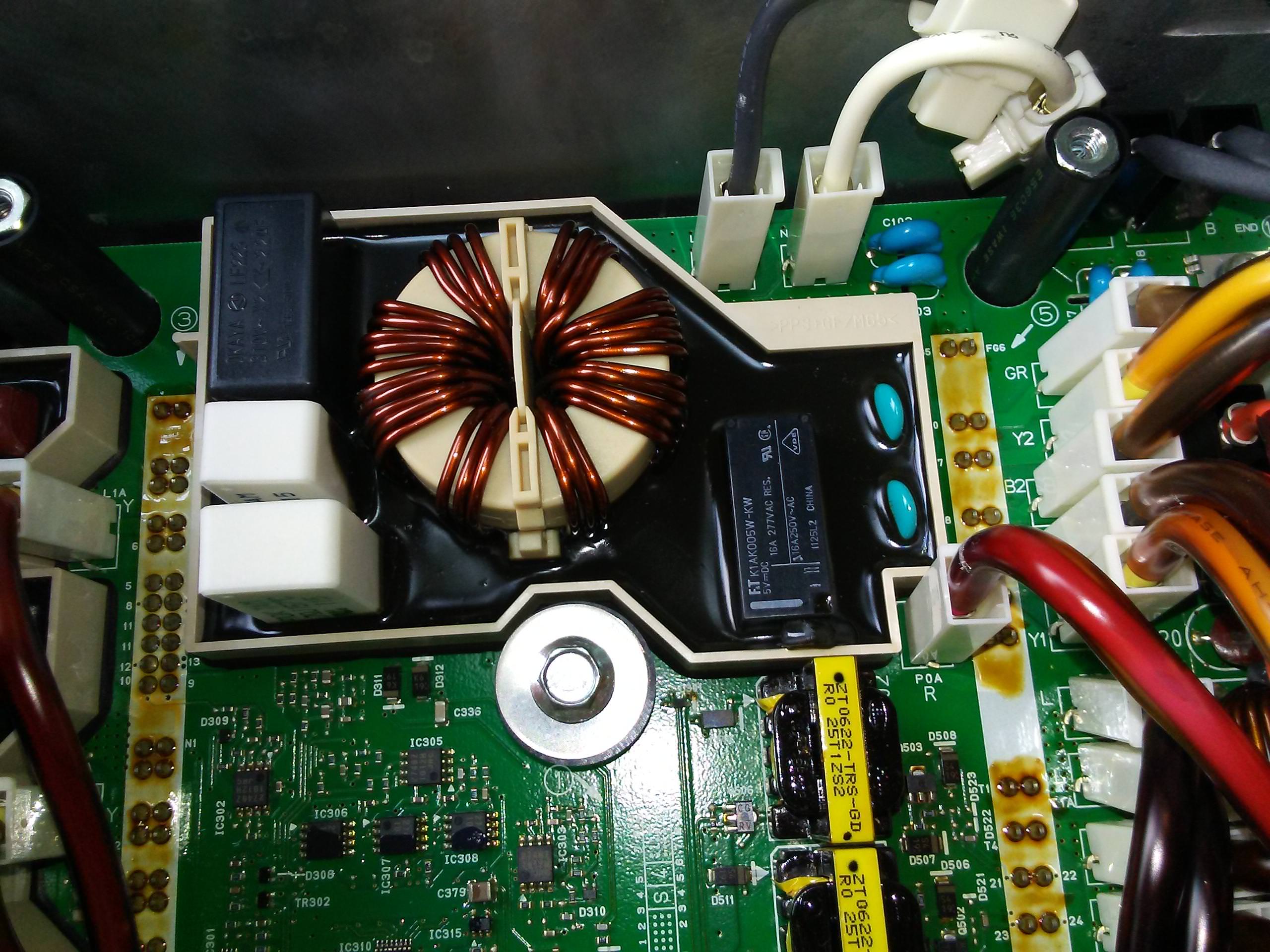
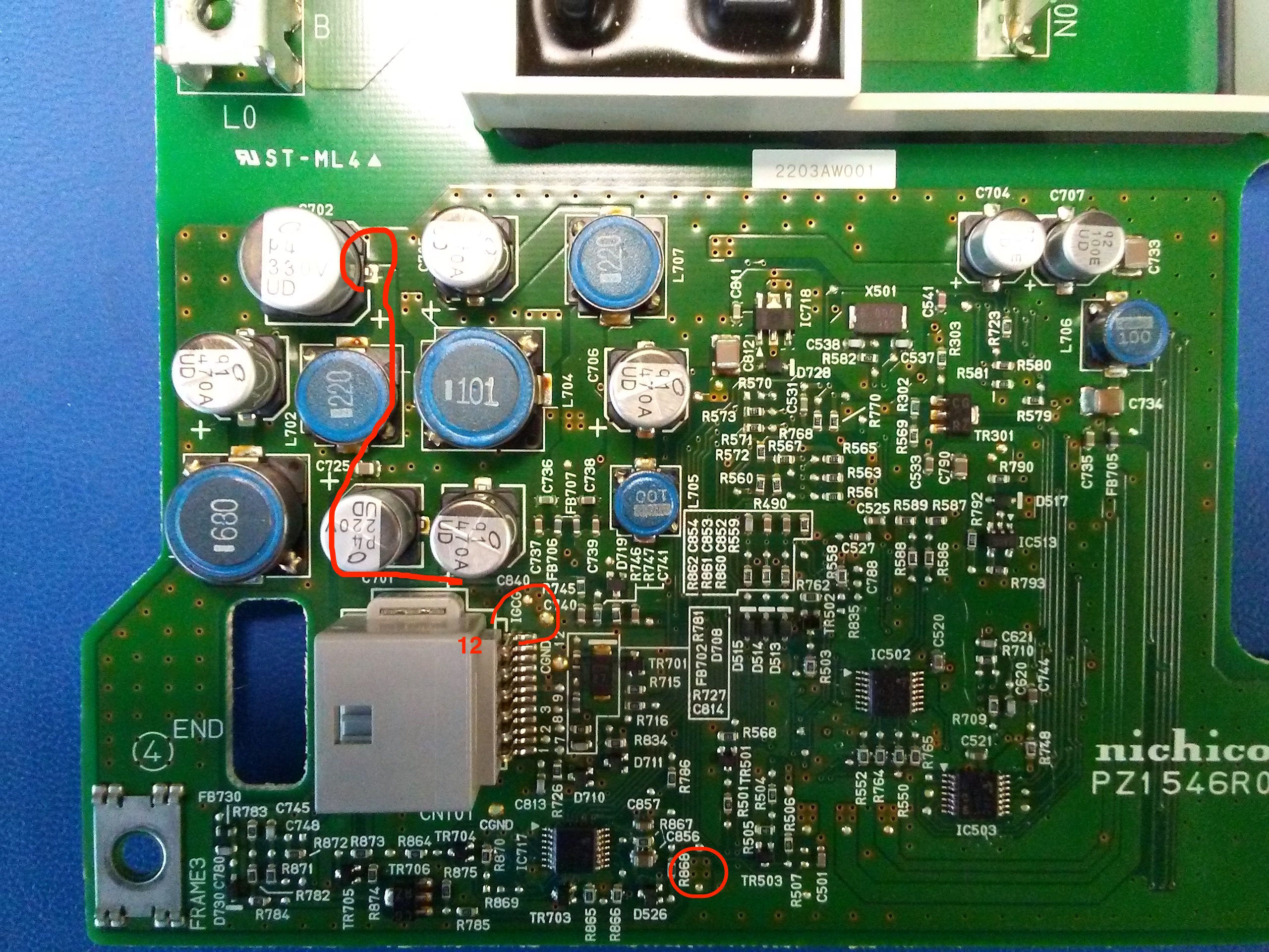
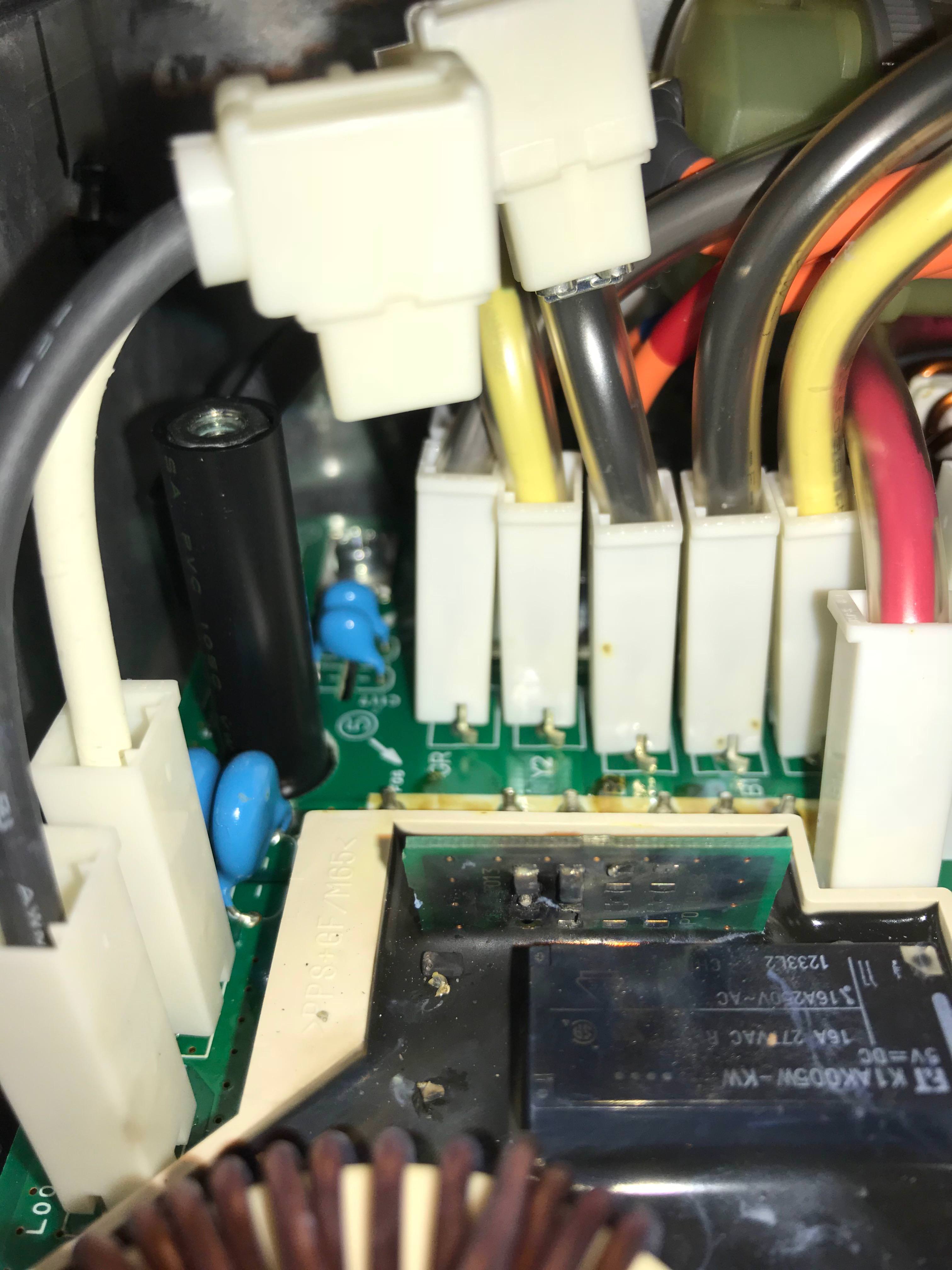
After successful charging all the way to 100% for 2-3 times at 8 A I tried charging at 14 A and it stopped after 30 min and the same problem started again. After few 30 min charges it finally charged from 50% to 100% during 3 h at 8A. So the problem was intermittent, sometimes it charges, sometimes it stops. I checked the battery and it was 12,6 V after leaving overnight. After turning on the lights for about 1 min and waiting for another 2 min the voltage was 12,3 V, so quite ok. I didn't measure the battery capacity (have no battery tester) but I finally spotted another label on the battery which indicated that the battery was installed in dec 2021. So the marking of nov 2022 was probably the end of warranty period, not when it was recommended to change the battery. With only 2 years old battery it is unlikely that the battery is the issue. So I decided to open the OBC. The 2.2 mF capacitor next to the ceramic resistors is definitely blown. It is hard to see from the photo (a better photo is coming when the board is removed) but it is swollen on the side next to the resistors and puked on one of the resistors. I am in the process of removing the lower board now. I saw a similar issues in this thread and will review those but some quick questions here before I go to bed:
1. Would the blown capacitor result in the issues I experienced (intermittent charging that stops after some time)?
2. Is it likely that the capacitor failure was caused by another issue which also needs to be solved?
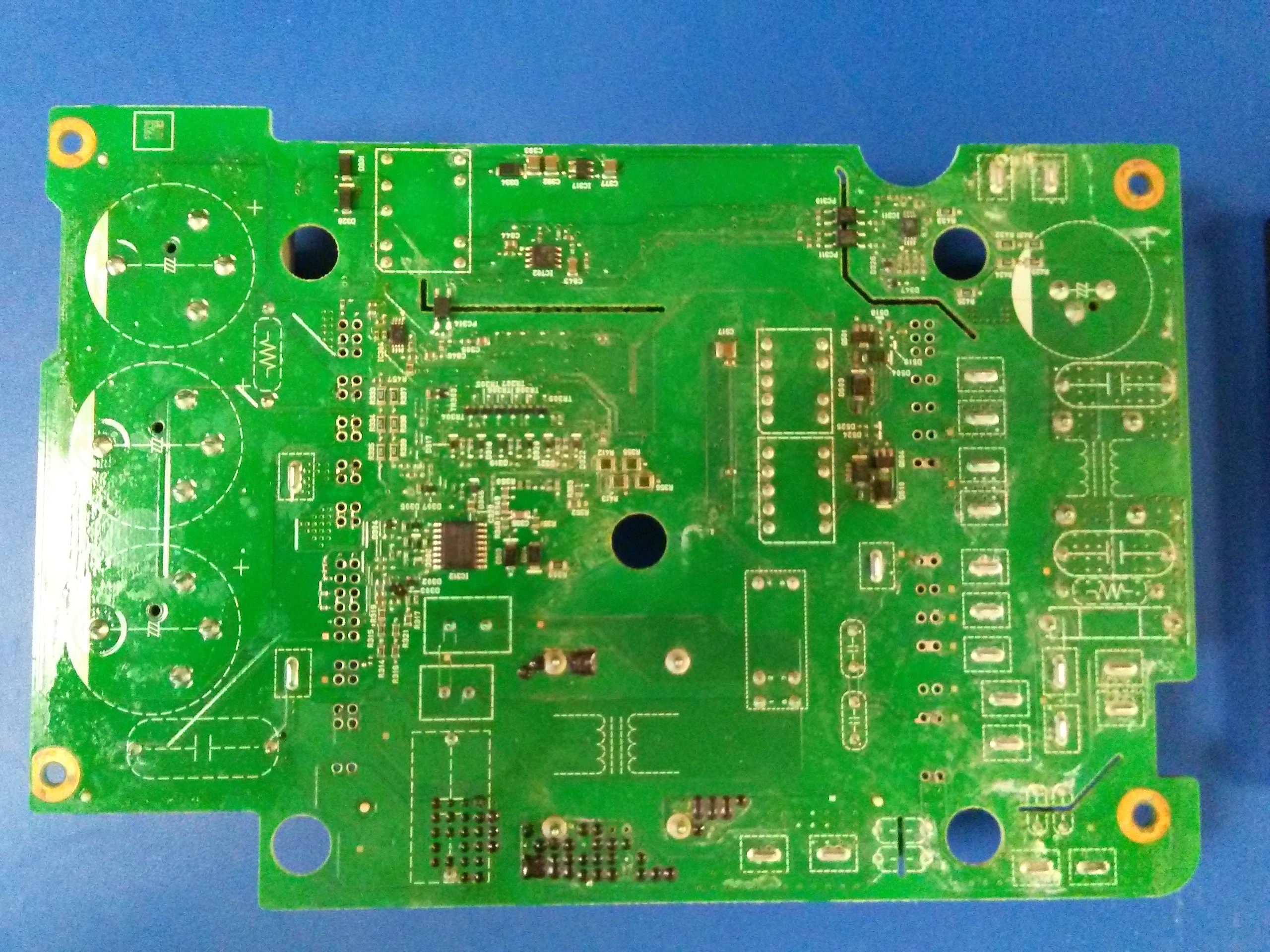
3. Does the Waffle plate need to be desoldered for soldering a new capacitor? Can the old one be just ripped apart to reveal the contacts and solder to those?
4. Which capacitor to buy? The marking says 310 V, which is kind of strange, with 230 VAC in Europe the peak voltage is 324V, shouldn't the capacitor be rated to that/higher voltage? Is it ok to buy a capacitor rated for a higher voltage? It should be ok with a higher capacitance, right? Any brand/type recommended?
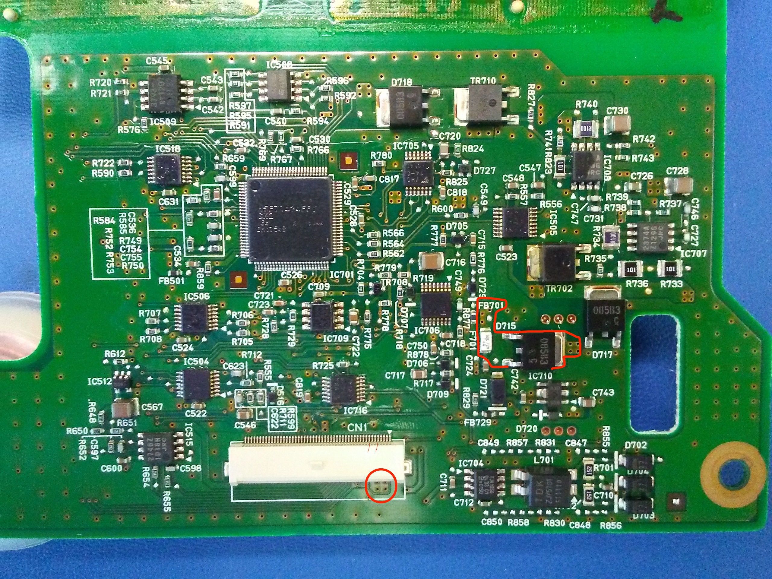
Also, I spotted some corrosion probably due to moisture coming through a plastic plug. Some residue ended up on the lower board. Is it common? I plan to clean it and silicone the plug in place
 . Charged at 8 A all the way. After that probably around 5 charges at 8 A from 30% to 100% and once at a public charging station at 3,1kW max. No problems so far, no stops. Fingers crossed.
Thanks for the report back.When connecting back the 12 V battery tightened the clamps firmly and just gave it a slight wiggle just to be sure it sits good ... and the negative terminal was loose.
Thanks, it's on ebay.de, https://www.ebay.de/itm/325986290718. Bidding starts at 500 Euros. A bit expensive, considering the whole charger could be found for $500.Here is the link to the spare part on Ebay
Hybrid IC für Onboardladegerät 9499A437
Ebay Artikel No:
325986290718