The Troubleshooting and Repair for On-board Charger (OBC) Thread

Mitsubishi i-MiEV Forum

Help Support Mitsubishi i-MiEV Forum:

This site may earn a commission from merchant affiliate links, including eBay, Amazon, and others.
Hi all,
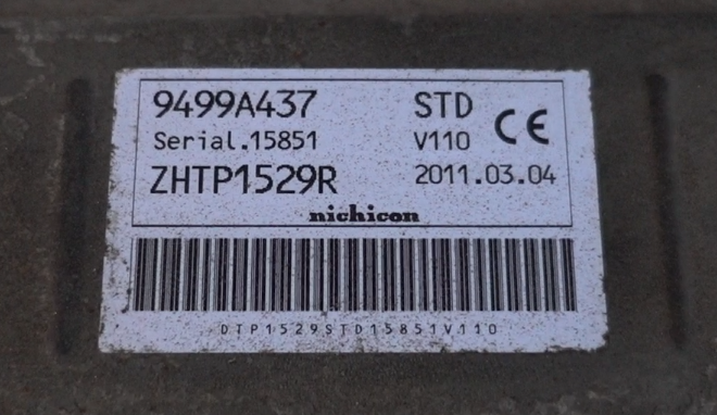
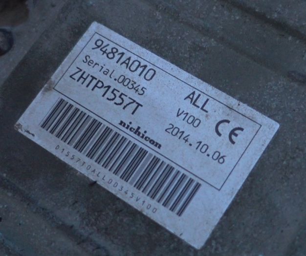
I posted a few weeks about a 2011 Peugeot Ion with a faulted OBC. I have now replaced the V110 2011 Charger, with a V100 2014 unit. It was not so straightforward, the HV connector, 12V DC/DC connector, and water coolant lines did not match up, but I got creative and made it fit. Happy to report that the newer charger works :cool:

Old:
ASdEsY5.png


New:
7PnJu5X.png


Will post a video shortly...
 
Hey People,

I tried to repair my third OBC, but stupid like people sometimes are, i reversed the L and The Y1 and then the ac-circuitbreaker B16 shuted the device of.
Since that i am unable to charge and at this time not sure anymore, how exactly the situation was, when i plugged the AC-cable in again.

The Situation now is that i have disassambled the waffleplate to check, if I crashed it.

On that picture it should be the pins 6 and 7 on the right side, which i reversed.
https://drive.google.com/file/d/1tHilCxdM7tmisq-a1U_R6NnYbFyOVV85/view

can someone give me advice, on which pins with a multimeter or this LCR-T4 https://www.ebay.de/itm/232563927160?hash=item3625e3e878:g:Xq0AAOSwKtlZlkiL i need the measure what, to find out, if the waffle plate is faulty or not?

If it should be good, i will reassamble it and then try step by step fixing other components.

At this point i found a crashed resistor, the big one with 4,9 Ohms made of ceramic.
All the caps are often faulty are good (2,2uF, both 1nF) because i replaced them before reversing the wires.
Now i checked them again and the relay also is fine.

While checking the relay i'm not sure, if i killed D301. What should the multimeter say in the different directions, if it is fine?

It is only the bottom board which is faulty.
The top board in connection with another bottom board works.

And Is there a way to post pictures here?

Best thanks for your support.
 
Where is AC circuit breaker B16 located? i'm not familiar with B16 and don't understand.

If you have tried 3 OBCs in this same car, then i suspect you have an external problem such as with the EVSE or AC Mains voltage supply or wiring, etc. You will need to get to the root cause of that problem before blowing up additional OBC units and parts. You will need to exercise extra caution and attention to details so as to not cause new problems, some of which are irreversible and not easily repaired, such as the waffle plate.

What country are you located and what is your best language? Maybe one of the other miev forums would have someone that could help you locally.

What is your knowledge, skills and abilities with electrical and electronics troubleshooting and repairs? What electrical tools do you have and your ability and skill to understand how to operate and measure with them?

There is much information in this forum thread to assist someone to make some repairs, but it requires a certain level of electronics knowledge and abilities. Hopefully you can get the necessary information and make a successful repair, but i am very limited in my free time right now.
 
Mucker said:
On that picture it should be the pins 6 and 7 on the right side, which i reversed.
Ah. That means that a pair of diodes would be placed across each of the two transformers' outputs. It's hard to say what this would have done; it certainly will have stressed the diodes, and possibly also the IGBTs driving the tranformers.

can someone give me advice, on which pins with a multimeter ... i need the measure what, to find out, if the waffle plate is faulty or not?
Find pairs where there are single diodes between them. For example, N0 to T7. The diodes should show about 0.3-0.4 V drop with the positive lead on the anode (the triangle end) and the negative lead on the cathode (bar end). It should read open circuit (OL or similar) with the leads reversed.

Unfortunately, there is a connection in the middle that is not accessible. So you have to get creative. You should see no conductivity in either direction from T7 to T8 or T6 to T5 (these are the most likely problem areas). Then T7 to T6 you should see two diode drops (0.6 to 0.8 V one direction, infinite the other), and similarly T7 to T5, T8 to T6, and T8 to T5, N0 to P0, N0 to T6 and T5, T7 to P0 and T8 to P0.

Test the IGBT back diodes; if these are normal 0.3-0.4 V drops, they are likely OK. Like diodes, they should be infinite in the other direction. Example: single drops 15/16 to T4, double drop 16/15 to P. Gate to emitter should read as 1kΩ in both directions (use the resistance range, not diode range for this).
 
Hey People thank you for your Advice.

I measured with the LCR T4 Mega:

N0 to T7 Uf=474 mV C=474 pF
N0 to T8 Uf=474 mV C=471 pF

T7 to T8 Uf= / mV C=260pF

T6 to T5 Uf= / mV C=300pF

T7 to T6 Uf=945 mV C=322pF
T7 to T5 Uf=945 mV C=330pF

T8 to T6 Uf=941 mV C=324pF
T8 to T5 Uf=941 mV C=330pF

N0 to P0 Uf=945 mV C=492pF
N0 to T6 Uf=945 mV C=371pF
N0 to T5 Uf=945 mV C=381pF

T7 to P0 Uf=945 mV C=407pF
T8 to P0 Uf=945 mV C=412pF

15/16 to T4 Uf1=527pF, Uf2=528pF

So the Waffleplate seems to be okay, right?
 
Hey People,

I'am not enough into electrical components, to repair this thing alone.

So I would like to know, if here a some people, who would try to repair it as a job for money.

Because the car without charging unit is not that usefull.

I would be happy about every tip.
 
Where are you located?

From your previous posts it seems that your 4.7 Ohm ceramic resistor had blown and that the waffle plate seems okay.

Do you have several defective OBC units? Maybe they can be used for spare parts.
 
Hey,

I'am located in Germany.

I have three others cars like this, but they are in small carsharing use. But for short I'am able to check and change some components.

A new 4,7 ohms resistor I odered.

While Testing the Relay, I think I blown D301.
If I measure now while this is built in, I get 60,5 ohms resistance in both ways.

Should I desolder D301 for testing or can someone say, if 60 ohms are normal?

Thank you very much for the support.
 
To test the diode it would need to be removed from the circuit.
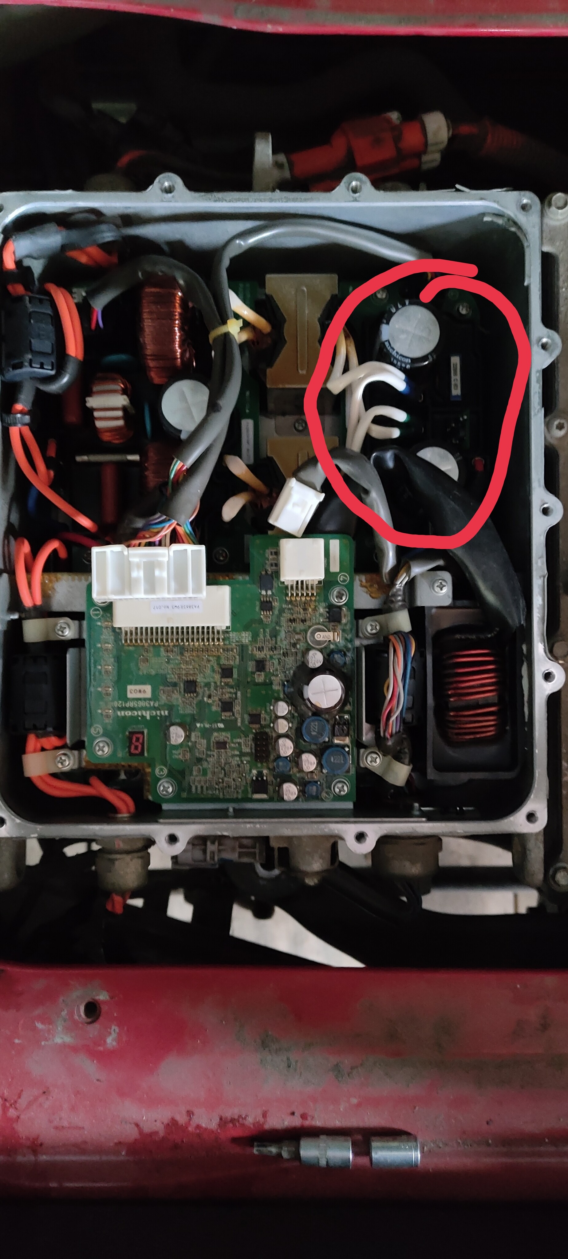
On my board i get the same 60 Ohms reading in both directions; this is because the diode is in parallel to the relay coil, so you are just reading the coil resistance.

Why do you suspect the diode? If it were shorted then the reading would not show 60 Ohms; if it were open it would show the 60 Ohms, then it would not prevent the relay from operation, but it would lack the freewheeling diode protection when commanded to OFF.

To test the relay you must put +5V at the end with the "bar" line, and return on the opposite end; this is in the blocking direction for a diode, it should not conduct thru the diode. See the picture in post #1 of this thread.
 
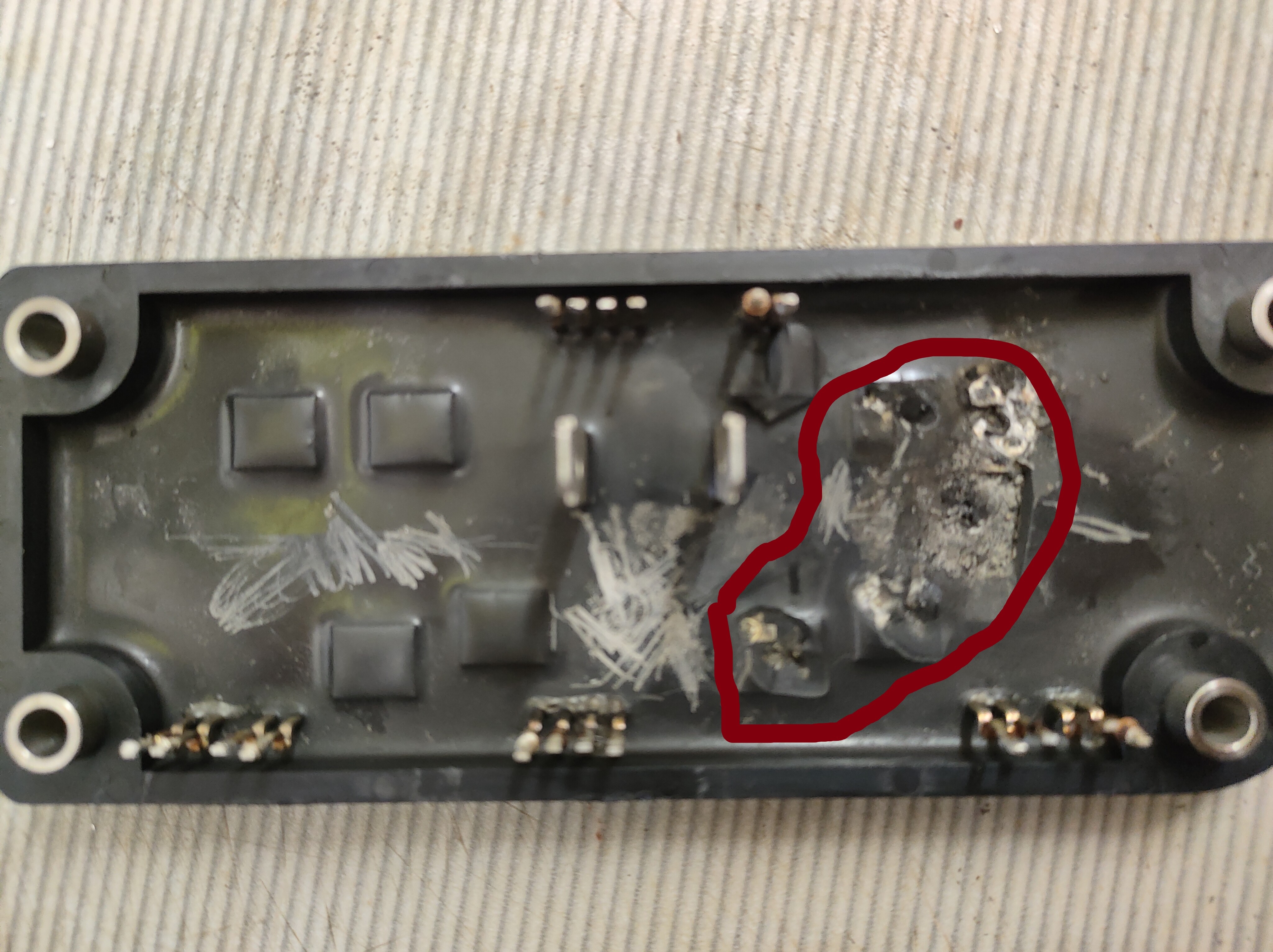
Всем доброго дня. Владею mitsubishi i-miev. В один момент перестала заряжаться , вскрыв зарядный модуль увидел следующее. На нижней плате под эпоксидным компаундом сгоревшие элементы. Сервисов и хороших электриков в городе нету. Помогите определить какие элементы стоят , и как это исправить.
https://wampi.ru/image/Rj3coiihttps://wampi.ru/image/RjsRouf
https://ibb.co/Tbn3NJ4
https://ibb.co/VtSkFLb
В данный момент пытаюсь снять эпоксидным компаунд.

Edit by JoeS: Google Translate -

Good day everyone. I own a mitsubishi i-miev. At one point, it stopped charging, opening the charging module, I saw the following. There are burnt elements on the bottom board under the epoxy compound. There are no services and good electricians in the city. Help determine what elements are worth, and how to fix it.
https://wampi.ru/image/Rj3coiihttps://w...ge/RjsRouf
https://ibb.co/Tbn3NJ4
https://ibb.co/VtSkFLb
At the moment I'm trying to remove the epoxy compound.
 
Good day everyone. I own a mitsubishi i-miev. At one point, it stopped charging, opening the charging module, I saw the following. There are burnt elements on the bottom board under the epoxy compound. There are no services and good electricians in the city. Help determine what elements are worth, and how to fix it.

Photo Links...
At the moment I'm trying to remove the epoxy compound.

The photos were not available with those links, but maybe a moderator will be able to move the discussion posts from the DC/DC converter thread over to here.
 
https://wampi.ru/image/RjsaTcI
https://wampi.ru/image/Rjsa3Ei
Предыдущая загрузка фотографий не прошла. Пробую снова отправить фото в данный чат.

Edit by JoeS: Google Translate -

Previous photo upload failed. I'm trying to send a photo to this chat again.
 
Okay those links are working.
IMG_20220618_185847.jpg


IMG_20220620_195710.jpg


Link to Philsuth's post on page 76 with disassembly photos of this same model OBC. The damaged board here is the PWM Inverter board with the switching transistors. Looks like half the board has blown away one of the H-bridges.

http://myimiev.com/forum/viewtopic.php?p=43401#p43401
 
Да , там такой же блок zhtp1500r.
Но плату там разбирали другую, просвечивая ее. У нас таких приспособлений нету, магазин радиодеталей находится в другом городе. Вот и прошу помощи , кто сталкивался с таким , и какие элементы нужно поставить , чтоб машинка снова заработала.
Сам в электротехнике не сильно понимаю. Помогите.

Edit by JoeS: Google Translate -

Yes, there is the same block zhtp1500r.
But there they dismantled another board, translucent it. We do not have such devices, the radio parts store is located in another city. So I ask for help, who faced this, and what elements need to be put in order for the machine to work again.
I don't understand much about electrical engineering. Help.
 
This will be a very difficult or impossible repair due to the epoxy.

Here are four options to consider, along with thoughts on success.

1, Remove the epoxy of the Junior Waffle Plate (JWP) and replace the transistors.

2. Find a used OBC and swap out the entire JWP.

3. Find a used OBC in a salvage yard and replace the entire OBC.

4. Find a used OBC from a later model year, e.g. 2011-2012, and replace the entire OBC. This may involve some coolant line routing,


There is a risk in all of these when buying used parts/boards/units, that hopefully it is intact and working. i have bought used units that later were found to be broken or had failed boards; and in other cases bought units from a salvage yard of wrecked cars in which the OBC was good and working.

Another difficulty with your OBC besides the epoxy, is to understand what other board or component might be damaged? When the H-bridge circuit failed in the JWP, what other circuits might also have been taken out? Without knowing the cause of your failure it is an unknown situation of whether just replacing the transistors in the epoxy would fix it or if some other element is faulty too.

The failure of the parts in the waffle plate is very rare, only a few cases have been reported, but Nobody has been successful at making a repair of a failed waffle plate such as you have experienced. So that is another consideration for which option to pursue.

Hope this helps,
kenny
 
Back
Top