Now MR BEAN won’t charge!

Mitsubishi i-MiEV Forum

Help Support Mitsubishi i-MiEV Forum:

This site may earn a commission from merchant affiliate links, including eBay, Amazon, and others.
coulomb said:
My guess is electrolytic capacitors coming to their end of life, and going high internal resistance and/or low capacity.

Some photos I've seen have the plastic no longer covering the tops of the capacitors (so that the full diameter of aluminum is visible from above), which suggests a lot of heat. Electrolytics hate heat; it ages them. Hopefully, it won't be like the Elcon EV chargers, where electrolytic capacitors are protecting the switching MOSFETs or IGBTs.

Good eye to catch that, and it appears that those caps are mounted in a bed of the black sealant. Here is a troubleshooting thread for the charger/converter box:
http://myimiev.com/forum/viewtopic.php?f=23&t=4079&p=36346#p36346
 
J bought my 2012 with 50,000 km (30,000 miles) on it so I don't know its history.

For the past two years I have been charging it only from 120V at the L1 (8A?) rate.

It would be interesting to see if there is any correlation between predominantly used charging rate and charger failures. Are higher charging rates causing more failures?
 
veimi said:
Are higher charging rates causing more failures?
MR BEAN has been almost exclusively charged on L2, though in a cool climate, and the capacitor tops in the low mileage replacement charger looked just as bare as the 80,000 mile unit it replaced.
 
veimi said:
J bought my 2012 with 50,000 km (30,000 miles) on it so I don't know its history.

For the past two years I have been charging it only from 120V at the L1 (8A?) rate.

It would be interesting to see if there is any correlation between predominantly used charging rate and charger failures. Are higher charging rates causing more failures?

An interesting question, factors work both ways. Lower power levels on L1. But much less up time for the charger on L2

Perhaps if everyone with a failure could give their most common charge voltage, a pattern will emerge.

Aerowhatt
 
Aerowhatt said:
An interesting question, factors work both ways. Lower power levels on L1. But much less up time for the charger on L2

Perhaps if everyone with a failure could give their most common charge voltage, a pattern will emerge.

Aerowhatt

I am presenting the following as a thought experiment. Other may chime in with real numbers.

Assuming that the charger has the same efficiency say 90% at both the L1 and L2 charge rates, for every KW passing through the charger 900W is put into the battery and 100W are dissipated elsewhere as heat.

The L2 charge level is approximately double the L1 rate, which means that the wasted energy of the L2 rate must be dissipated in 1/2 the time of the L1 rate which implies that when using the L2 rate, much more heat is being generated although for a shorter time.
 
L1 versus L2 charging thought experiment

Level 1 at 120 vac (rms) is ~170V peak, and this will provide about 160 VDC when rectified.
Level 2 at 240vac is ~ 340V peak, and makes about 320VDC when rectified.

Since the pack needs 360VDC to get charged, this requires a Boost stage in which the rectified DC gets chopped into AC and run thru a transformer to pump it to a higher AC voltage, which then gets rectified and filtered to produce the necessary 360VDC.

In level 2 the rectified DC is much closer to the required 360, so it could be said that the Boost stage and transformer don’t have to work as hard to make up the difference.

With good engineering design and proper selection of components with margins for voltage, current and temperature, there should be little to no failures. It may be that there is a weak link in the components that is suffering an early mortality (5 yrs into a 10 yr life) that was not considered in the original design.

In my experience of repairing electronics it has been failed capacitors that are high on the list of culprits. Fortunately they are relatively inexpensive and sometimes easy to replace.
 
Ours was replaced 2 years ago, so a 2 year old part, not sure the 5 years age thing is generally correct. If you look back in this thread there were a couple of failures in 2 year old cars too.
 
Aerowhatt said:
veimi said:
It would be interesting to see if there is any correlation between predominantly used charging rate and charger failures. Are higher charging rates causing more failures?

An interesting question, factors work both ways. Lower power levels on L1. But much less up time for the charger on L2

Perhaps if everyone with a failure could give their most common charge voltage, a pattern will emerge.
I kinda doubt you would ever see a meaningful pattern evolve. Maybe a better question would be do you plug in to recharge immediately after driving the car, when the inverter charger is already heated up, or do you wait several hours and plug in when everything is cool? Do you recharge during the heat of the day with the car sitting out in the sun, or do you recharge overnight parked in a cooler garage? For the past 6 years since the cars were new, I've been trying (98% of the time) to never plug them in immediately after driving, more to let the battery pack which isn't water cooled come down to ambient temps before charging, thinking (hoping) I'm doing something to extend the life of the car

The inverter/charger is water cooled, isn't it? Shouldn't the cooling system be keeping the internal temps in an acceptable range?

Don
 
Don said:
kinda doubt you would ever see a meaningful pattern evolve. Maybe a better question would be do you plug in to recharge immediately after driving the car, when the inverter charger is already heated up, or do you wait several hours and plug in when everything is cool? Do you recharge during the heat of the day with the car sitting out in the sun, or do you recharge overnight parked in a cooler garage? For the past 6 years since the cars were new, I've been trying (98% of the time) to never plug them in immediately after driving, more to let the battery pack which isn't water cooled come down to ambient temps before charging, thinking (hoping) I'm doing something to extend the life of the car

The inverter/charger is water cooled, isn't it? Shouldn't the cooling system be keeping the internal temps in an acceptable range?

Don

You are probably right, but it might be interesting anyway. I'm trying to remember the liquid coolant flow pattern as it does pick up heat along the way. If I'm remembering right it comes back from the radiator to the charger/DC to DC then goes to the inverter and then the motor. If so, then the charger would get the coolest coolant. But it would still be significantly hotter overall right after driving. I'm very lucky that our cars are parked in a cooled garage (off topic, but it is cooled for free) so ambients in the garage top out in the high 70's F. No matter how hot it is outside, 102-ish pretty often in June. Like you I think, it makes sense to charge after a rest and everything cooling off especially the battery cells. It may not help at all, but we can be sure that it doesn't hurt! Ours almost always charge in the middle of the night with built in timers in the Siemens EVSE's. That's good for the utility company, the cars and us.

Aerowhatt
 
coulomb said:
jray3 said:
Here's the spec sheet for our 20A fuse under the inverter inspection cover. Still haven't found an online vendor.
I believe that PEC might stand for Panasonic Electronic Components ...
I was WRONG. It stands for Pacific Engineering Corporation. Here is a detailed drawing of the fuse, in case we might find a suitable replacement from more accessible manufacturers.

https://www.pecj.co.jp/fuse/files/Drawing_EVFG_7215A.pdf

From the web page for their Φ7.2 mm fuses:

https://www.pecj.co.jp/en/fuse/ev/evfg_72.html

It says that the part number for the 20 A model is 2759. This seems way too short to me.
 
jray3 said:
Here's the spec sheet for our 20A fuse under the inverter inspection cover. Still haven't found an online vendor.
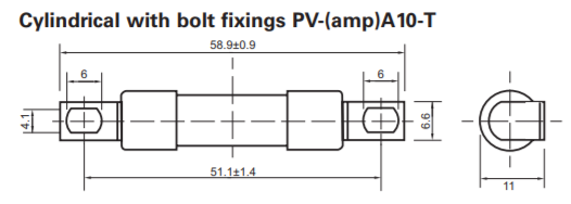
The nearest equivalent I have found so far isn't great. It's a Bussmann/Eaton PV fuse, part number PV-20A10-T, which is surprisingly rated at 33 kA or 50 kA of interrupt capability (what panels can manage anything like that? Perhaps in a commercial solar farm).

It's available from Mouser US: https://www.mouser.com/ProductDetail/Bussmann-Eaton/PV-20A10-T?qs=sGAEpiMZZMvnfWYzRsH6EbYZ2445BpOV

It costs around US$30 and won't be in stock for several weeks (as of this post in early July). Digi-Key have it as non-stock item, meaning they will order 10 of them for you if you want, and the unit price is even higher (around US$358 for quantity 10). Newark/element14 and RS-Online don't seem to stock it.

It's also too big: it's a 10x38 mm fuse, so the holes are 51 mm apart (49 mm minimum assuming M4 bolts). [ Edit: It's probably a near-exact or exact fit; see this post. ] So you could cut off the ends and nibble or drill the slot to take the presumed 45 mm spacing of the bolts. Totally non-ideal, but if Mitsubishi are out of stock, this might be a solution for the adventurous and/or desperate.

yeezoop.png


Littelfuse don't seem to have anything suitable. The closest seems to be their 504 series: http://m.littelfuse.com/~/media/electronics/datasheets/fuses/littelfuse_fuse_504_datasheet.pdf.pdf

But these are leaded fuses (you could bend the pigtails into a loop), and the killer is the interrupt rating: only 400 A @ 420 VDC. The slightly low voltage rating would I believe be adequate, but I think you'd want every bit of the 2000 A interrupt rating of the original PEC fuses.

[ Edit: Added image; Bussmann -> Bussmann/Eaton ]
 
Back
Top