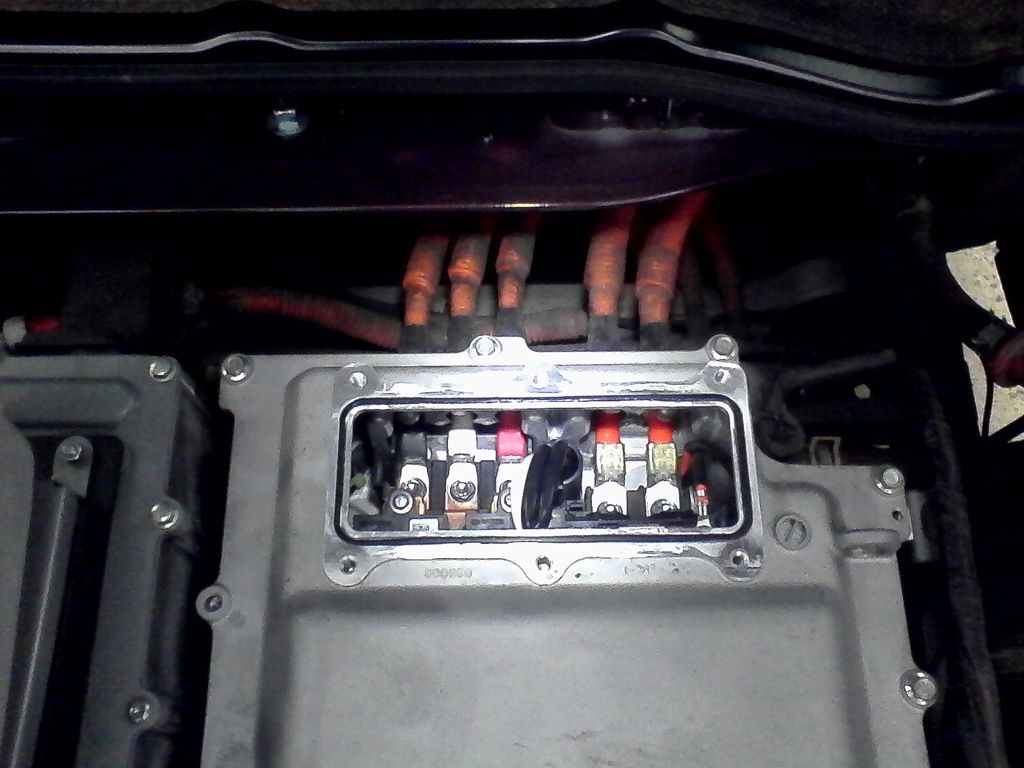
Also known as a motor drive inverter, here are some photos and details of the internal components. Thanks to Ben Nelson for making some utube videos of his ordeal with a saltwatered miev as i bootleg his photos.
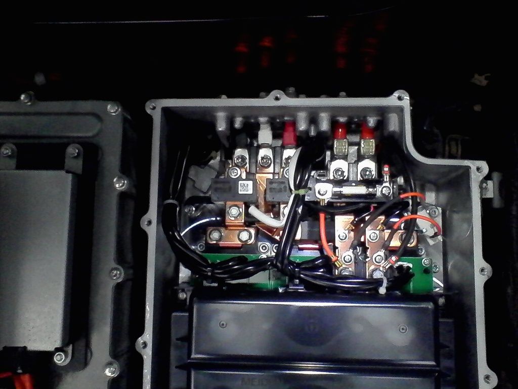
Here is a view from the top of the upper chamber with the high power components, where you can see the black, white and red motor phase terminals and the main pack HV lines with + closest to the red phase and - on the right. The black plastic cover thing is a large ShiZuki 800uF 450 VDC capacitor, aka condenser.
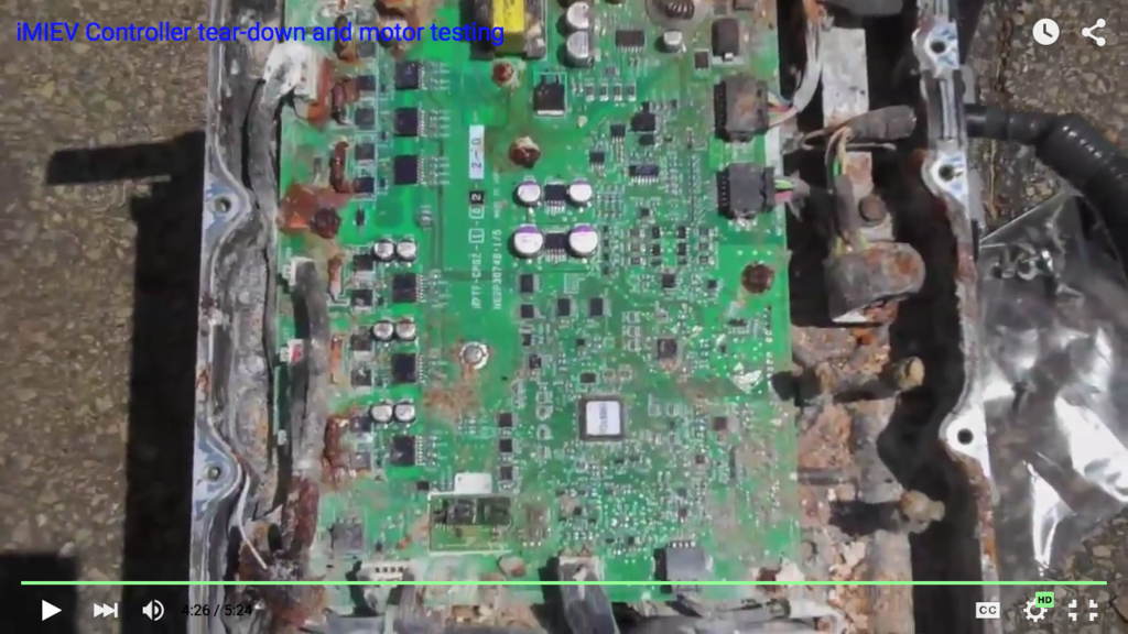
Here is a view of a crusty crab control board located in the bikini bottom chamber below the liquid-cooled heatsink. The MCU recall is likely due to some component on this board.
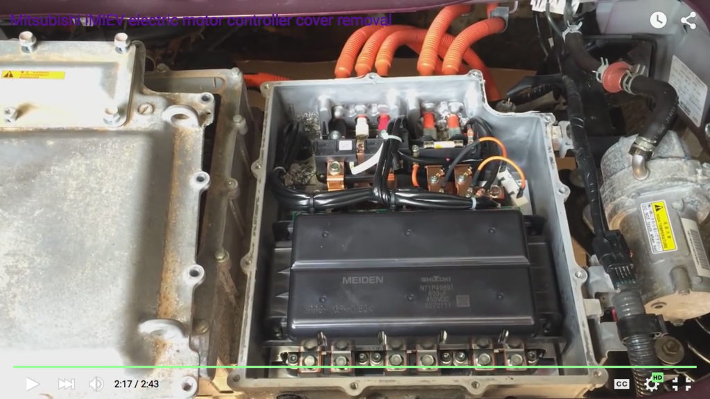
Here you can see 2 Nippon Ceramics Co current sensors on the buss bars (1.5mm, 0.060" thick) of the black and red motor phases. The white rectangular device at the right is a 56 kOhm power resistor to bleed the high voltage from the condenser after the key is switched off, which will take about a minute. A couple of other HV lines are fed off the main pack buss bars (one has an inline fuse ??, one is a small sense line).
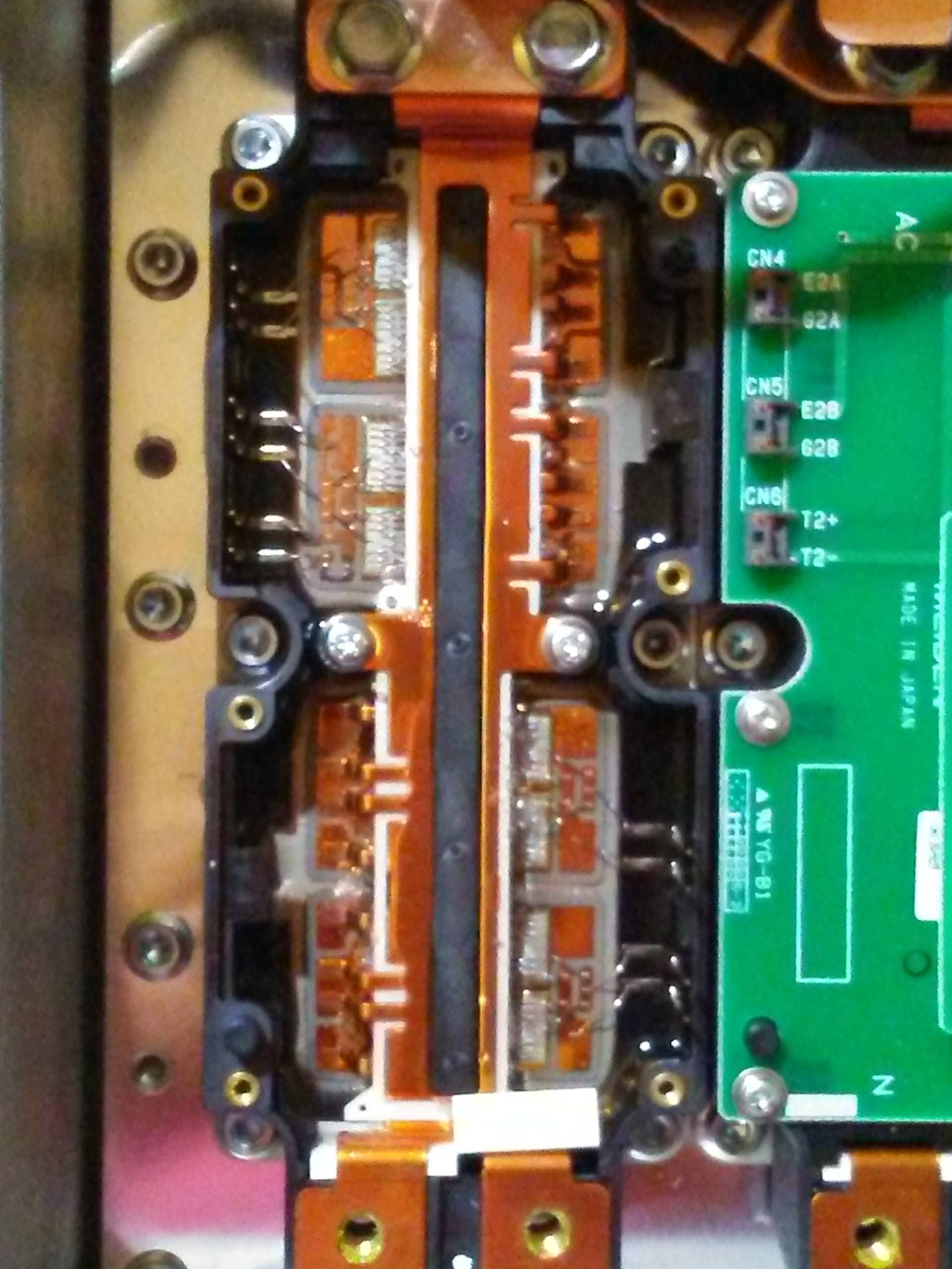
This is the business end of the three phase bridge that switches and routes current thru the motor. There are 3 boards located below the condenser and attached to the Hitachi 600A/600V IGBTs (MBM600JU6B). Four wires to each board, 2 for the top and 2 for the bottom gate drivers, so an aftermarket hotrodder could tie in here to drive the motor with something like a custom arduino controller...
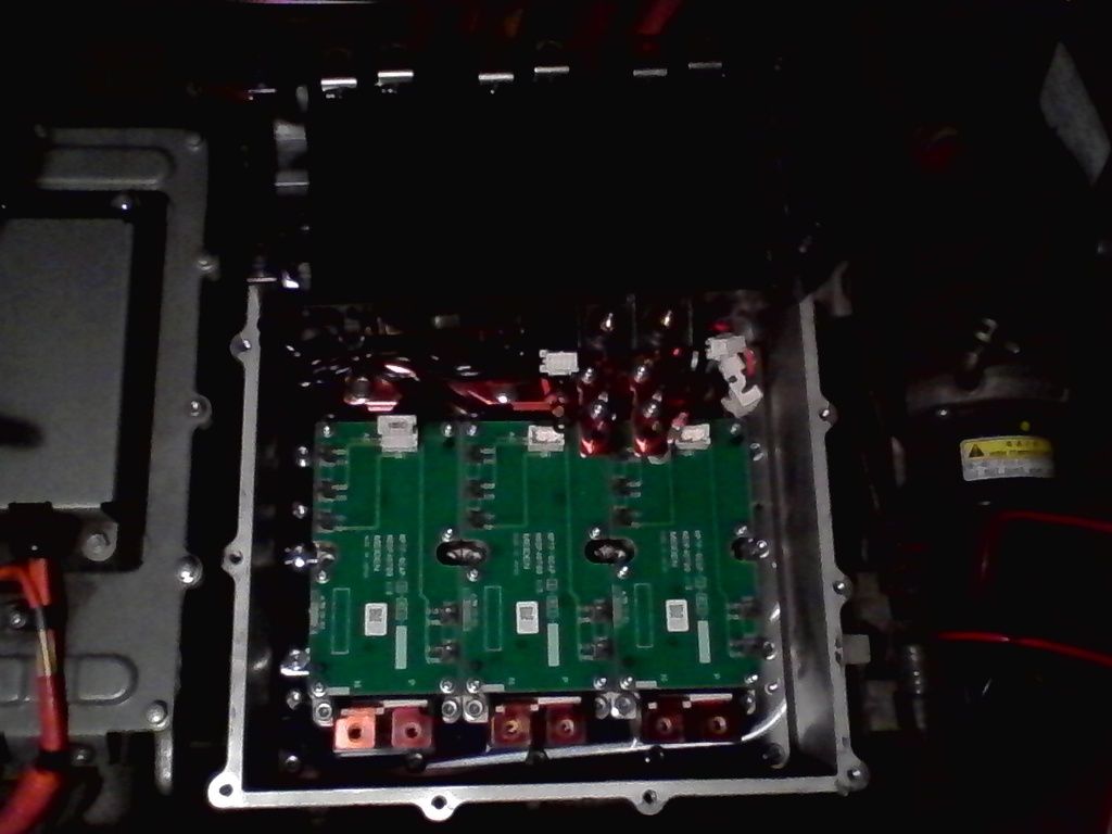
These seem to be compact well-designed motor controllers with plenty of margin in the high power components. They could easily be repaired if necessary and if the replacement components could be sourced.
Here is a view from the top of the upper chamber with the high power components, where you can see the black, white and red motor phase terminals and the main pack HV lines with + closest to the red phase and - on the right. The black plastic cover thing is a large ShiZuki 800uF 450 VDC capacitor, aka condenser.

Here is a view of a crusty crab control board located in the bikini bottom chamber below the liquid-cooled heatsink. The MCU recall is likely due to some component on this board.

Here you can see 2 Nippon Ceramics Co current sensors on the buss bars (1.5mm, 0.060" thick) of the black and red motor phases. The white rectangular device at the right is a 56 kOhm power resistor to bleed the high voltage from the condenser after the key is switched off, which will take about a minute. A couple of other HV lines are fed off the main pack buss bars (one has an inline fuse ??, one is a small sense line).

This is the business end of the three phase bridge that switches and routes current thru the motor. There are 3 boards located below the condenser and attached to the Hitachi 600A/600V IGBTs (MBM600JU6B). Four wires to each board, 2 for the top and 2 for the bottom gate drivers, so an aftermarket hotrodder could tie in here to drive the motor with something like a custom arduino controller...

These seem to be compact well-designed motor controllers with plenty of margin in the high power components. They could easily be repaired if necessary and if the replacement components could be sourced.


