Is my battery dying ?

Mitsubishi i-MiEV Forum

Help Support Mitsubishi i-MiEV Forum:

This site may earn a commission from merchant affiliate links, including eBay, Amazon, and others.
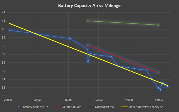
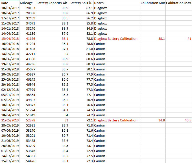
As expected, some time after the battery calibration the BMS has made an upwards adjustment of about 1Ah from 32.7Ah to 33.6Ah.

So it seems that when you do the full battery capacity measurement in Diagbox it initially sets the "usable" reported Ah capacity to about 2Ah below the actual measurement of the worst cell in the pack, (33 vs 34.8) and then some time later it will adjust that so that the usable is about 1Ah below the actual capacity of the worst cell.

Here are my latest figures:

uc


uc


Beside the one off upwards correction it is still counting down 0.1Ah fairly regularly, I've seen it drop 0.4Ah in less than a month, which is a lot higher than expected. In short my weak cells seem to be failing rapidly so I've decided that I am going to attempt a cell swap of the four worst cells.
 
So I finally bit the bullet and committed to replacing four cells in my pack, as the precipitous loss of capacity at what I believe is an accelerated rate continues, and I know that I'm going to really struggle for range this winter if I don't do something about it, not to mention the slow rapid charging the high resistance cells cause.

I ordered them from Second Life EV Batteries in the UK, for £212 including shipping and they arrived in a few days.

I can't say that I'm terribly happy with the packaging they arrived in - basically two layers of cardboard box and some bubble wrap, I was expecting some sort of wooden or otherwise protected box, as one serious drop by the courier would have done significant damage to the cells... :roll:

As it is, they look OK so I have started testing them one by one:

uc


As my charger/discharger is designed for considerably smaller cells and has a maximum charge rate of 6 amps and maximum discharge of 2 amps it's going to take a while, probably about a week to test all 4 cells by the look of it. :lol:

The cells arrived charged to 3.96 volts, so first I have to charge them up to 4.1 volts, which took about 8 hours due to the charge rate tapering off more than it should due to the resistance of my charging leads, (as this prematurely puts the charger into constant voltage mode when the actual cell is not yet to 4.1 volts) and this added about 12Ah of capacity, so from that the cells must have arrived at approximately 75% SoC.

I'm now discharging the first cell to 3.0 volts and after more than 12 hours it's still at 3.88 volts and has discharged about 18Ah so I should know the result for the first cell by tomorrow. After that I will then be doing a storage charge to bring the cell back up to 3.8 volts for storage until it's ready to go into the car, and when I swap the cells I'll discharge the pack in the car until the good cells are also at 3.8 volts (which is approx 30% SoC) as it's far quicker and easier to bring the cells in the car to the same SoC as the replacement cells than doing so with the slow charger.

I plan to use the method discussed over on speak EV of lowering the battery pack down on threaded rods to a small trolley which I will then wheel into the work area in my garage to disassemble the pack out of the weather. This is all conditional on the cells having adequate capacity after testing - otherwise they're going back!
 
Took a while but the first replacement cell has been tested and I'm glad to report it's in good health. :)

I'm actually recording two different Ah capacity figures from the test of each cell - one from 4.1 volts down to 3.63 volts, and another figure discharging all the way to 3.0 volts.

The reason I did this is because while the raw cell capacity of 50Ah claimed for a new cell according to the data sheet is actually based on a discharge to 2.75 volts, (my charger will only discharge to a minimum of 3.0 volts so I used that) the car itself only ever discharges the cells down to about 3.63 volts or 320 volts for an 88 cell pack, and at 3.63v per cell the pack is considered to be at 0% SoC and the car will shut off.

This is probably done to make sure that the voltage under heavy load does not dip below 3.0 volts, as it would if the unloaded voltage was allowed to go much below 3.63 volts.

So while a discharge to 3.0 volts will give an idea of the raw capacity of the cell outside of the car and in relation to Yuasa's specs, a discharge to 3.63 volts should give a more realistic "usable" capacity that probably matches up with that reported by the BMU, and is thus the figure that matters when compared to what the BMU is reporting.

As it turns out there's only about 3Ah of capacity between 3.63v and 3.0v anyway, so effectively the car is leaving about an 8% buffer below "0% SoC", or perhaps a 10% buffer if you compare it to a discharge to 2.75v. The following voltage curve during a 1.3A discharge shows that 3.63 volts is very close to the "knee" in the voltage curve where the voltage drop starts accelerating:

uc


I've highlighted 3.58 volts on the graph to obtain the time marker not 3.63 because there was about a 5mV drop in voltage across the cables at the 1.3A discharge rate so the cell measured at the terminals was actually 3.63 volts at this time. Looking at the same time mark on the capacity graph we can see that the usable capacity down to 3.63 volts is almost exactly 40Ah:

uc


Full capacity of the cell discharging to 3.0 volts is 43.573Ah. As the BMU reset capacity of the cells is 45.8Ah that means this cell has a SoH of 40/45.8*100 = 87.3%.

Also 43.573/50*100 = 87.1% - a very close match, which fits my theory that 50Ah is the full capacity of the cell when new and 45.8Ah is the "usable" capacity of a new cell in a car due to only discharging to 3.63 volts in operation.

According to the BMU battery calibration I did recently the very best cells in my pack still have a usable capacity of 40.5Ah and the worst ones that I am replacing are down around 34Ah, so the new cell regardless of whether you take the 40Ah or 43.6Ah figure is at least as good if not better than the best cells in my pack, let alone the bad ones they're replacing. :mrgreen:

I'm now doing a 3.8v storage charge of the cell before moving onto the next one, and fingers crossed the other ones are as good as the first...

By the way if you're wondering why my graphs don't begin at zero capacity and the 4.1 volt starting voltage its because the discharge cycle took so long at 1.4 amps that the time counter on the charger unit actually reached 65535 seconds and overflowed, resetting back to 0 seconds and starting the graphs anew from that point. :lol: Fortunately the Ah capacity figure did not reset or rollover as well.

So while the summary page says the discharge took 54908 seconds, it was actually 54,908 + 65,535 = 120,443 seconds or about 33.5 hours. :twisted:
 
Second cell tested and also good - within 0.1Ah of the first cell - probably within the margin of error for the measurement technique. I'm surprised in fact at how closely the first two cells tested are matched.

It makes you wonder what happened to the cells in my pack to cause the best and worst ones to diverge by more than 6Ah despite being in much the same environment - identical charge and discharge current since its a series string, only the temperature of the different cells would differ, and even then they would only differ by more than a few degrees if the car is being driven hard and/or rapid charged a lot - and I rarely rapid charge.

Manufacturing tolerances/defects that only come to light after a certain amount of cycling ? Different degradation profiles due to uneven temperature distribution around the pack ? Repeated deep discharges causing any initial tiny imbalance to be blown out of proportion over time ? (A cell already weaker will be discharged to a lower SoC than good cells and will suffer incrementally more degradation as a result, increasing the spread between good and bad cells progressively)
 
According to user piev, all cell failures are due to a lack of electrolyte. He has studied numerous technical papers looking at cell life factors and boiled it down to this simple conclusion.

These battery cells operate by reversible chemical and electrochemical reactions involving the anode, the cathode, the electrolyte, and a microscopic SEI layer. Every cycle consumes a tiny bit of electrolyte and eventually things get out of balance.
 
Hi DBMandrake,

I'm wondering how you have gone with this transplant of the 4 replacement cells?,
I've been keenly following your posts about this, as I have a 2010 i-MiEV which I am considering individual cell replacements for.
I have access to a hoist and ease of removing the battery though, :p, so it's more about purchasing good second hand cells (I'm based in Melbourne, Australia).

Did you finish your cell testing of these 4 cells?, and did you swap them into the existing pack?
Cheers!
:mrgreen:
 
SylphH said:
Hi DBMandrake,

I'm wondering how you have gone with this transplant of the 4 replacement cells?,
I've been keenly following your posts about this, as I have a 2010 i-MiEV which I am considering individual cell replacements for.
I have access to a hoist and ease of removing the battery though, :p, so it's more about purchasing good second hand cells (I'm based in Melbourne, Australia).

Did you finish your cell testing of these 4 cells?, and did you swap them into the existing pack?
Cheers!
:mrgreen:
Yes, I finished testing all the cells a few weeks ago - as I could only charge them at 6 amps and discharge at about 1.3 amps it took nearly a week to test all four, and by then I forgot to update this thread... :twisted:

The results were:

USABLE capacity 4.1 to 3.63 volts (3.58 during 1.3A discharge due to cable resistance) and FULL discharge to 3.0 volts.


Cell A - 40.0Ah USABLE, 43.573Ah FULL
Cell B - 39.9Ah USABLE, 43.471Ah FULL
Cell C - 40.8Ah USABLE, 44.543Ah FULL
Cell D - 40.6Ah USABLE, 44.353Ah FULL

As mentioned earlier I suspect the BMS will report closer to the first figure for each cell, but in any case that is still good as the very best cells in my car are only 40.5Ah and the worst ones are around 33Ah.

The hold up now is getting a small trolley built to go under the battery pack to wheel it out (fairly easy, some timber, caster wheels etc, as the pack is only 164Kg) and figuring out a way to get the car up good and high yet still stable. (Not so easy)

Rather than trying to jack it up approximately 50cm on the axles (as I don't really have anything to put under the axles that would be stable at that height) I think I'd rather raise it up on the wheels, for example lower the wheels down onto some wooden sleepers (which I have lying around the garden) however I need to get it at least 30cm higher off the ground to have enough clearance which would be three sleepers high, so I'm not sure how easy or stable that would be.

So I'm still trying to figure out an easy and practical way to get the car up a lot higher than usual on a driveway - normal stands/ramps aren't high enough (only about 20cm) unless I put them on top of a layer of sleepers. I suppose I could get a second set of ramps so I have ramps for all wheels and jack the car up and onto the ramps on top of sleepers.. :?

If anyone has any good ideas of an easy way to get the car raised up about 30-40cm higher than normal I'm listening...!

The last couple of months I've been strapped for cash so after buying the cells I had to put the project on hold for a bit but the winter weather will be here soon so I need to get a rattle on and get it done now.

BTW if you're swapping individual cells, I presume you've diagnosed some individual low capacity cells using Canion as I have ? Do you have a MUT-III or have access to one ?

After a successful cell swap you'll need to initiate the "battery calibration" routine so that it will correctly re-measure the capacity of the pack as a whole and update the working Ah figure. If you make a big improvement to the usable capacity of the pack it will not learn this properly without the intervention of the battery calibration routine, which means you'll get little or no increase in usable range as the BMS won't allow you to use the extra capacity.

As I have the PSA version of the car I use Diagbox/Lexia 3 to do this.
 
Hi Simon,

Here in the USA 12" wide x 16" long x 8" high concrete blocks cost about $3 each.
A stack of two of these with a piece of 3/4" ply on top gets you up to around 16" , or about 40cm.

Including the plywood cost would be under $50.
I would take some fiberglass-reinforced tape and tape together the blocks and plywood.

If you can scrounge/borrow some blocks to stack, and some plywood to cut, cost could be lower.


Cross-stacking the sleepers you have could work well.

Are you anywhere near Aberdeen?

Thanks and good health, Weogo
 
A couple of weeks ago our CZero was in for service. Part of the service was a measurement of the battery capacity. I’ve written the results up in a post on the battery capacity testing discussion. The shop also told me that their test instrument showed that the expected capacity of a new battery is 48Ah. While this is less than the nominal capacity of 50Ah, it is more than the 45.8 reported by the Diagbox. I still believe that a new cell right off the Yuasa assembly line at an operating temperature of 30oC has a capacity of 50Ah. However in the few months it might take to get the cell to the car and the car to the dealer that capacity may very well decrease to 48Ah due to storage degradation. And if the operating temperature is less than 30oC when tested the battery might show as little as 45.8 Ah. In other words, the measuring instruments are programmed so that we will not be disappointed when we measurer the capacity of a new battery.
 
CZeroOwner said:
A couple of weeks ago our CZero was in for service. Part of the service was a measurement of the battery capacity. I’ve written the results up in a post on the battery capacity testing discussion. The shop also told me that their test instrument showed that the expected capacity of a new battery is 48Ah. While this is less than the nominal capacity of 50Ah, it is more than the 45.8 reported by the Diagbox. I still believe that a new cell right off the Yuasa assembly line at an operating temperature of 30oC has a capacity of 50Ah. However in the few months it might take to get the cell to the car and the car to the dealer that capacity may very well decrease to 48Ah due to storage degradation. And if the operating temperature is less than 30oC when tested the battery might show as little as 45.8 Ah. In other words, the measuring instruments are programmed so that we will not be disappointed when we measurer the capacity of a new battery.
I think you're overthinking this and you'll find the difference between 48Ah and 45.8Ah is simply down to choosing the minimum discharge voltage when performing the test. In other words you'll get a different result depending on how you define the test...

The Yuasa datasheet states the cells are 50Ah if discharged all the way down to 2.75 volts. The car does not do this! ;) The car only discharges the cells down to about 3.63 volts, which is well above the minimum voltage that the cells can be taken down to. There are multiple reasons for this - one is that this is open circuit voltage, and the cell has to maintain enough charge so that the cell voltage doesn't go dangerously low under full load from the motor. Therefore you have to be more conservative.

When I measured my 2nd hand replacement cells (still waiting to go in the car) If I measured down to 3.63 volts I got around 40Ah, if I measured down to 3.0 volts I got around 44Ah. So there is at least 10% of the cells potential capacity below the 3.63 volts that the car is willing to go down to.

The BMS Ah figure reported by Diagbox will almost certainly be based on the usable capacity between 4.1v and 3.63v, not 2.75v. However if the cells are tested on an external discharge tester that will take them to a lower voltage you'll get a higher Ah figure that more closely matches the manufacturers claims for the cell.
 
My battery was tested in the car. I wasn’t there but the procedure they told me they followed sounded very much like the one you described for the Diagbox.

Could it be that the Diagbox knows that 3.63 volts is equal to a SoC of 10% and that the Ah it measures between 3.63 and 4.1 is 90% of the battery’s true capacity? The number it gives you is in fact an estimate of the capacity between 2.75 and 4.1 based on this 90% number. I don’t see how we can compare capacities if all the measurements depend on different voltages.

David
 
CZeroOwner said:
My battery was tested in the car. I wasn’t there but the procedure they told me they followed sounded very much like the one you described for the Diagbox.

Could it be that the Diagbox knows that 3.63 volts is equal to a SoC of 10% and that the Ah it measures between 3.63 and 4.1 is 90% of the battery’s true capacity? The number it gives you is in fact an estimate of the capacity between 2.75 and 4.1 based on this 90% number. I don’t see how we can compare capacities if all the measurements depend on different voltages.
Yes exactly. The car (and Canion) will report 0% SoC at about 3.63v per cell and shut off the car when the cells really have about 10% capacity left, if they were to be discharged down to below 3.0 volts. However that bottom 10% can't be used because the cells would go under voltage under heavy load, eg when you accelerate and this would damage them.

To use that last 10% of capacity you have to progressively limit the current drawn to a lower and lower level to remain at a safe voltage, which is not useful in a car. Instead of doing this the car just uses a higher shutoff voltage - at 3.63 volts (no load) even under full acceleration the voltage doesn't go below about 3.0 volts.

By the way I'm not sure if you read in another post of mine, but I discovered that there are two different triggers for turtle mode. One is if the SoC drops below about 10% (as reported in Canion) which is in reality close to 20% left in raw capacity, the other is any cell going below 3.0 volts even instantaneously during acceleration will also turn on the turtle lamp on the dashboard and limit acceleration.

Normally the 10% SoC threshold for turtle mode comes first however if the Ah figure in the BMS was way too optimistic for some reason, you might hit the 3.0v safety limit. This happened in my testing when I reset the Ah capacity to factory default and the battery ran out "sooner" than the BMS was expecting causing it to run the battery right down to 3.0 volts...
 
After many other unrelated delays (other car breaking down and needing repairs first, house renovation, family commitments, illness, bad weather etc...) I'm almost ready to drop the battery pack out of my car to swap four cells. I built the following trolley/dolly specifically matched to the size of the battery pack, and designed to be as low as possible to minimise the height I need to raise the car:

uc


uc


It's sized to allow the battery pack frame to overhang the trolley enough to let the threaded rods clear the trolley, also to allow jacks to get under the edge of the battery frame while it's still resting on the trolley:

uc


That means I can get a jack under the edge of the overhanging battery pack frame and lift it up off the trolley onto the threaded support rods if necessary. The eye hooks are to attach 4 ropes to allow me to pull the battery sideways out from under the car (with a bit of help!) and also into my garage for disassembly then back again. At an alleged 240Kg it hopefully won't be too difficult to move on 4 castor wheels!

So, just waiting for a fine weekend now - a tall order at this time of year as I was originally planning to do this job more than 2 months ago... :roll:
 
I spent this weekend removing the traction battery from my Ion and it is currently sitting in my (slightly less freezing than outside) garage. Plan is to actually disassemble the pack starting on Wednesday (my body needs a rest after two hard days working on it in the freezing cold) to swap cells and then refit it next weekend.

Will post a full write up with picture and results once its back in and tested however I wondered if anyone wanted any specific photos taken of the insides, dimensional measurements, tracing of wiring and so on while I have it all apart to add to the available knowledge on these traction battery assemblies ?

I will take a few photos of course but I know some things would have helped me make the removal easier if I'd known them before hand - such as the height of the pack from the bottom chassis to the top of the plastic cover.... (I ended up having the car higher off the ground than I needed which increased the time to lower the battery on the threaded rods!)

Oh, and it's very rusty down there. Large parts of the under body of the car are seriously rusted as there is no underseal to be seen anywhere... including the bottom side of the traction battery itself whose cross members have a couple of places where I can poke my finger through the rust! :shock: Nothing that will cause imminent structural integrity problems but disappointing none the less.

Also of the multitude of M6 bolts that hold the bottom plastic covers on approximately half of them snapped off at the head of the bolt even after using rust penetrant and after they were already turning. And I was only using a tiny 5" long ratchet! Soft as butter steel springs to mind... :roll:

Anyone have any tips on drilling out a large number of broken M6 bolt remains other than the obvious one of using a correctly sized small drill ? (I have a new, sharp 4.2mm drill bought just for this which I think will be about right)

To add to the knowledge base I did confirm one theory - Canion can still read all the cell voltages even when the high voltage safety link plug under the seat is removed. I thought this would be the case. Turning on the key with the link plug removed (or the entire traction battery removed, heh heh) does of course set the high voltage orange warning light on the dash, (as there is a small low voltage "sense" connector in the link plug as well that the ECU can read) but I'm sure it's nothing I can't clear with the diagnostic tool.
 
DBMandrake, thank you for the update. Pity about the rust (here in California, my 1967 Saab is still rust-free so I'm clueless) and the bolts breaking are just a PIA to drill out and remove. Looking forward to the photos and your writeup of the process!
 
Yes, sorry to hear of all the rust and broken bolts. Minimal salting here in the Pac NW for salmon recovery, so minimal rust down below.

The threaded rods area really just needed for safety and alignment purposes. I swapped my pack by jacking each end of the pack down/up 5 cm at a time and then finger-spinning the nut down the shaft before releasing the jack and moving to the other end. Wrenching on those nuts while they carry the load is a real drag... When properly aligned, I didn't even need to hold a wrench on the two locked nuts I had installed on the end of the shaft to act as a bolt head. I just held the shaft with one hand and spun the nut with my other hand. Gotta make sure not to unscrew the rod while backing off the nut.
 
That's my four cell swap completed and the car back on the road on Tuesday. :)

I took loads of pictures but posting them here is a real PITA as it's the only forum I use that doesn't support uploading attachments, and uploading them elsewhere and linking is a bit of a pain for lots of photos to be honest. :x

Apart from things like rusty bolts everything went fine except for one mistake I made - I matched the Voltage/SoC of the replacement cells at 20% SoC rather than 100%.

So as they charged up the newer higher capacity cells "fell behind" as they would need more charging to reach 100%. So at full charge they ended up 50mV lower than the other cells. (4.05 v instead of 4.1 volts)

Of course the cell balancing system valiantly spent 3 hours trying to balance the cells at the end of the normal charge cycle but finally had to give up after making little headway. 50mV less is approximately 5% of the entire capacity of the battery so assuming about 40Ah that is a 2Ah error in cell balancing between original and replacement cells.

With 100mA capable balance resistors it is going to take at least 20 hours of balancing time to correct this mistake! :roll: I tried using the "Voltage equalisation" procedure in Diagbox (which I believe is the same as the Cell Smoothing feature in MUT-III) however it aborted after less than an hour so the only option seems to be to simply let the balancing system pick away at it bit by bit at the end of every charge cycle, and it seems to be willing to do about an extra two hours of balancing after reaching 100% before timing out and ending the charge session without achieving balance.

The car is working fine but due to this the usable capacity will be limited by the imbalance so I'm probably not going to attempt the battery calibration procedure until after adequate balance has been established, which make take around a month.

Meanwhile the BMU has made a small Ah adjustment itself. The day after I refitted the battery it went down from 33.0Ah to 32.9Ah - which will just be modelled degradation, but then this morning after three days commuting totalling about 100 miles driving it bumped the figure up to 33.9Ah which is higher than it was when I removed the battery. :)

This seems to align with what happened during jray3's battery swap where the BMU would gradually bump the Ah up by 1Ah every few hundred miles, so it will be interesting to see where it gets to by the time I'm ready to do the battery calibration.

For those of you who have had your battery packs out before I have a piece of advice - check the rubber grommet/seal for the battery air intake is properly engaged in the bodywork!

It might not be immediately apparent but when you jack the battery up into place again it's impossible to properly engage the air intake grommet simply by raising the battery - the grommet will be partially crushed against the body and not sealing.

You must lift the carpet and remove the air duct from the grommet to the AC system to get access to pull the grommet through and engage its slot into the bodywork hole properly then refit the air vent. I have pictures detailing this.

If this is not done road spray may be able to enter the battery pack through the air vent.
 
By the way does anyone know the significance of the colour of the LEV50 cells ? Or is there no significance ?

My original cells are an olive green colour, my replacements are blue.... however online I have also seen purple and yellow!
 
Hello DBMandrake and hello to all others in this very interesting forum,

My name is Sandro from Milan, Italy. Sorry for my poor English. I own a C zero and I have 2 friends with C zero too.

My second hand C zero of 2011, has only around 24000 km, 14k of them driven by me since I bought it in Oct 2017.
I can drive my car for approx 90 km in winter and 110 km in summer.

I use Canion with ODB Link LX and in case of SoC around 10%, I have 2 weak cells with up to 100 /110mV of difference with the highest cells. My pack has some 36 / 38 Ah according to Canion.

As with my 2 friends we bought an i-Miev from wrecking, we have dismantled it all and took all parts as spare parts for our C zeros, we just throw away the chassis..... (you can image how happy is my wife with so many car parts in my cellar :).

Therefore we have the battery pack too (by the way, I confirm there is Hall sensor for DC current measurement inside the batt. pack and I think to adjust its output analogue signal would not be too difficult in case we need to change the all cells with much higher capacity...).

I tested all the 88 cells by two different milliohmeters and I can select the best ones based on the internal resistance (this varies from 1.49 to 1.73 milliohm with one milliohmmeter, with the other one 1.75 to 1.98 milliohm).

However a better device for capacity cell measurement would be opportune I think....

Can I ask you the following questions?

-If I understood well, you replaced 4 cells in your car last Nov 2019. But you did not charge them like the other cells. Now few months passed, so I guess the charge level of the 4 cells should be aligned to the rest of the pack. Or not?
How is the range now comparing before the swap?

-My weak cells are 53 and 57 according to Canion. How can I located them in the pack apart measuring the voltage cell? Is there any other way to locate them?

I added some photos hoping they can be seen.

Thanks to you and to all will help me with their replies and comments.
Ciao
Sandro

PS: I am sorry but I do not know the colour meaning, probably there is no meaning apart the production lot, but I think the kind guy in Holland (that I know him because I contacted him for other matter) could probably give you more info.
 
Back
Top