C-ZERO Fault code P1A2A

Mitsubishi i-MiEV Forum

Help Support Mitsubishi i-MiEV Forum:

This site may earn a commission from merchant affiliate links, including eBay, Amazon, and others.

Neo5

Member
Joined
Mar 21, 2024
Messages
12
Hello everyone,
I'm experiencing a breakdown on my 2012 C-Zero with a total of 110000km,
The car starts and goes into ready mode, as soon as I change gear P -> R / N or D, the light of the car with the exclamation mark appears, the car remains motionless no reaction to the pedal.
The 1st time the problem occurred the car had been stationary for 1 week outside (it rained a lot) and there was a bang at the rear when starting.

12V battery ok (less than a year old)
Car charges

fault code P1A2A

Anyone know the problem?
 
Welcome to the forum, sorry to hear of your trouble. We have never had this code reported that i can recall.

The P1A2A DTC refers to
  • Malfunction of the EMCU IGBT system
Unfortunately that is likely a blown Integrated Gate Bipolar Transistor in the motor control unit that you heard make the loud pop--that is what they do when shorted and blow.

There are 3 of them located below the big black capacitor in the MCU, and there is a thread here with pictures of the internal works of the IGBT.

https://myimiev.com/threads/motor-control-unit-mcu-details.2844/

i think this was posted before but i'm not finding it quickly, but here is the guts of one transistor
eJVJ7x7.jpg
 
Last edited:
Hello Kiev,

Thank you for all this information, not having found much on the internet you enlighten me a lot :)

I'll update the thead when I disassemble the MCU, if it confirms what you say

Do you think that just by replacing the transistor it is repairable? or if it is HS you must plan to replace the MCU
 
i think it is fairly easy to remove and replace a damaged transistor. i'm not sure where that part could be ordered but i haven't searched.

Of course another failure might be to the big black capacitor itself. Never seen or heard of that happening, but it would make a loud bang.

Basically you would need to remove the cover and inspect, check, test, verify the components, hopefully find a culprit and replace it. All the high power stuff is in the top plenum, the control and logic board is in the bottom plenum.
 
Hello

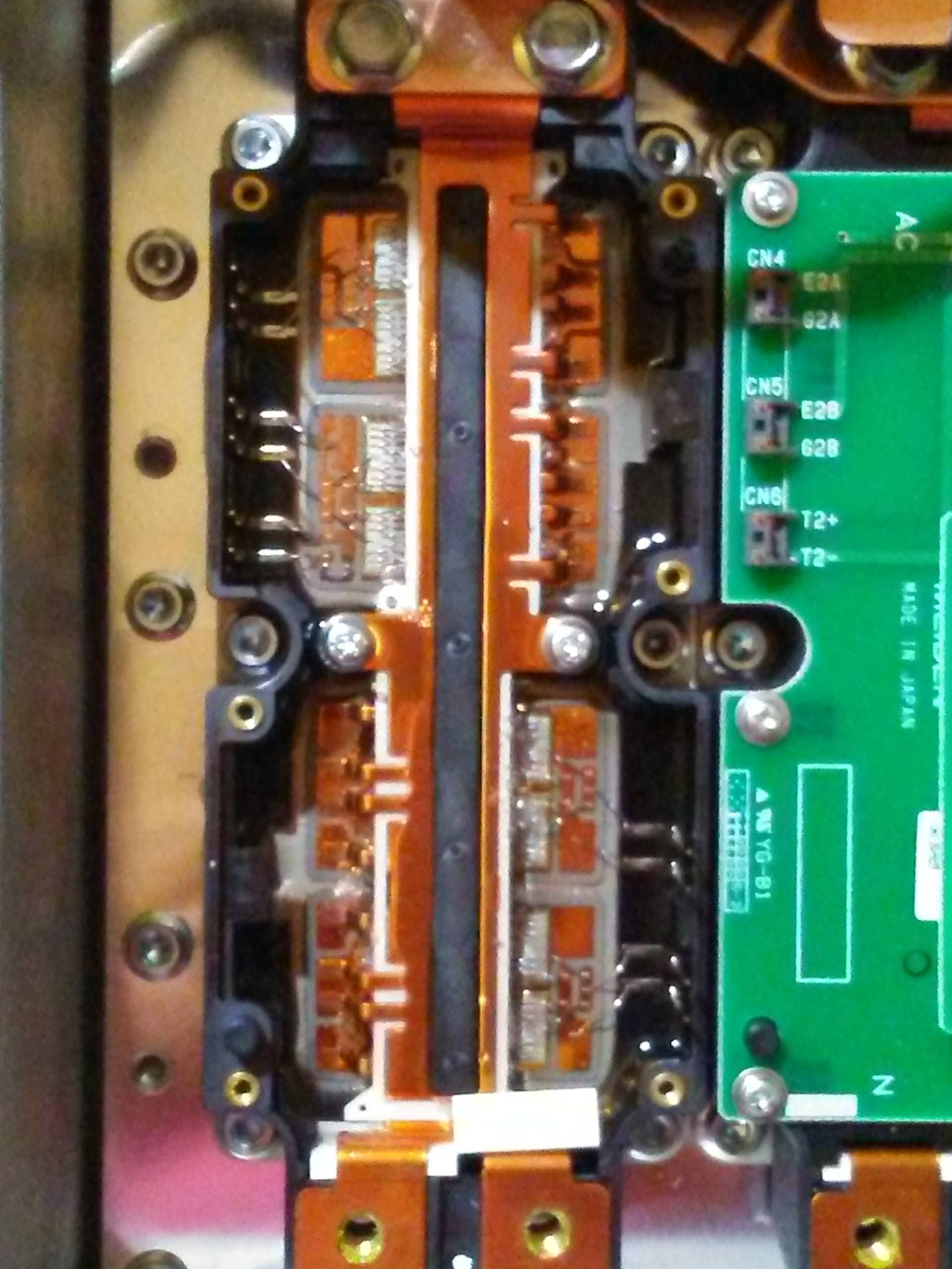
I found some time to disassemble the MCU.
Here are some pictures but i don't see anything special.
Except for this spot with a bubble and a black spot.
1000012682.jpg

Maybe you see something wrong?
 

Attachments

  • 1000012676.jpg
    1000012676.jpg
    73.8 KB
  • 20240330_133006.jpg
    20240330_133006.jpg
    77.1 KB
  • 20240330_181725.jpg
    20240330_181725.jpg
    89.7 KB
  • 20240330_181731.jpg
    20240330_181731.jpg
    77 KB
  • 20240330_181739.jpg
    20240330_181739.jpg
    95.8 KB
  • 20240330_181746.jpg
    20240330_181746.jpg
    79.8 KB
Last edited:
It looks blown to me, but can you get a closer picture for more resolution of just that upper section with the damage, to be sure?
 
Those are great pictures. The marked block appears as damage in that picture, but looks almost okay in the other one showing all three. You would need to be looking for broken or burned bond wires, or burned and blown out pads on the silicon. i looked at all three and couldn't find anything obvious except the red marked block--can't tell if the bond wires are damaged or not.
 
Last edited:
I found it on a Polish private sales site (like eBay)

When I ordered, the seller also had the mcu capacitor among the parts for sale.
 
Well, I've driven the car between 10 and 20 km, and after several restarts, it won't start now... the symptoms are identical to code P1A15.
 
Well replacing the IGBTs "repaired" the broken parts, but why did they fail to begin with is the question?

There is some fault that caused them to fail--maybe a shorted winding in the motor, motor winding varnish failure, some fault in the controller to accidentally misfire the gate drives, etc?

Make sure that your 12V battery is fresh and fully charged and verified to be good.

Are you actually getting the P1A15? Fortunately that is a different issue not directly associated with the IGBTs
 
That's a good question, but finding the source of the problem won't be easy, in my opinion, if the two problems are linked.

I don't know if this will help, but I've been having this non-normal behavior for a while now, when the car is running and accelerating or going from "D" to "R", the motor jerks.
I also noticed that when I replaced the IGBTs, the thermal paste had become liquid, similar to oil under the old IGBTs.

The battery is new from last year, but I'm going to check the voltage anyway.
As for the fault code, I don't have the OBD at the moment to confirm.

But I've already got to get the car home
 
I checked the car's fault codes.
After deleting all the fault codes, the car switched to ready mode and drove off.
After stopping the car and turning it back on, I again had a starting problem, code p1a15 on the computer.

By insisting, the car goes back to ready mode, otherwise the fault code is removed.
 
That sounds like good news, in that the IGBTs are fixed and working.

The P1A15 is due to the little HV isolation amplifier board in the bottom chamber of the MCU. It can typically be an intermittent fault that gets progressively worse over time until it will no longer go the READY. There is a thread that discusses this fault and repair options.
 
Thank you for your help,

I've read all the info on this subject on the forum and on the internet.

I don't like the resistor solution as much as many others. I don't think I've seen anyone use a variable resistor, in order to be able to adjust the value in case of drift over time, would it be a good idea?

I saw that @kiev you tried with a forum member to replace the components of the ISA215-HYD board, if I understood correctly without success?
There must be a component with a problem if replacing the board with an AD202KN works.

I don't know if we'll do the AD202KN solution, which costs a lot, but it's an easy solution.

@Gary12345 I am from France, you can contact me in private message, I am open to listen to the options available in uk
 
There were a few components that did not get swapped when we did that troubleshooting exercise, plus the oscilloscope setup was not ideal.

There are 2 separate reference grounds [HV and LV] on the hybrid board that must be observed and kept isolated; you must not measure across the planes (probe on one side with ground clip referenced on the other).

Also most scopes reference earth ground with the ground clip, so care must be taken when using bench power supplies.

The quickest approach to get back driving would be to add a parallel resistor (a Meg Ohm or two) on the input leg of the Op Amp, or even easier to solder would be to change a resistor in the voltage divider network. Then you might have some time to plan for a longer term solution.

divider network R211-R220
MCU HV resistor divider.jpg
 
Last edited:
Back
Top