Starting another thread to collect this information.
CMU board with labels,
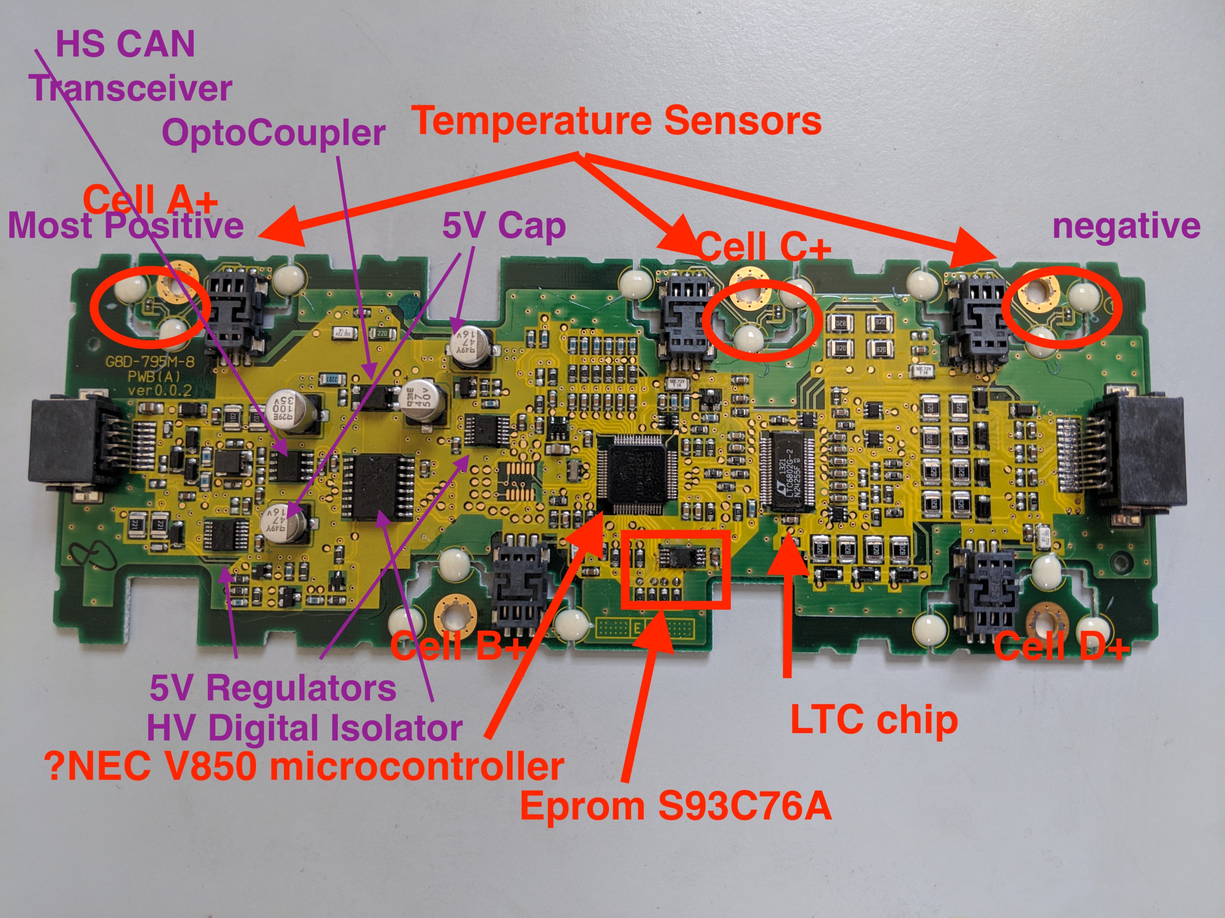
CMU board with labels,

Last edited:


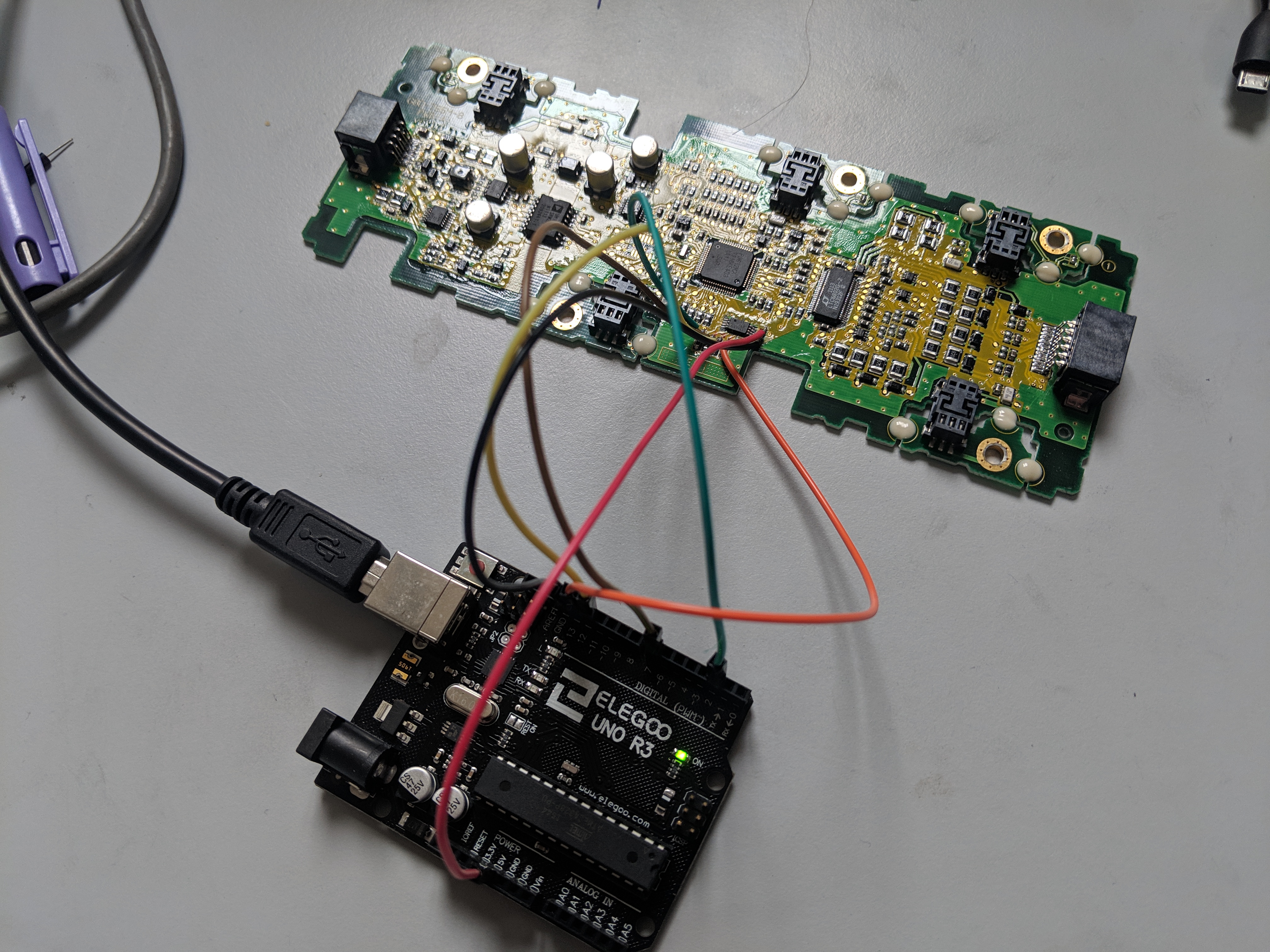
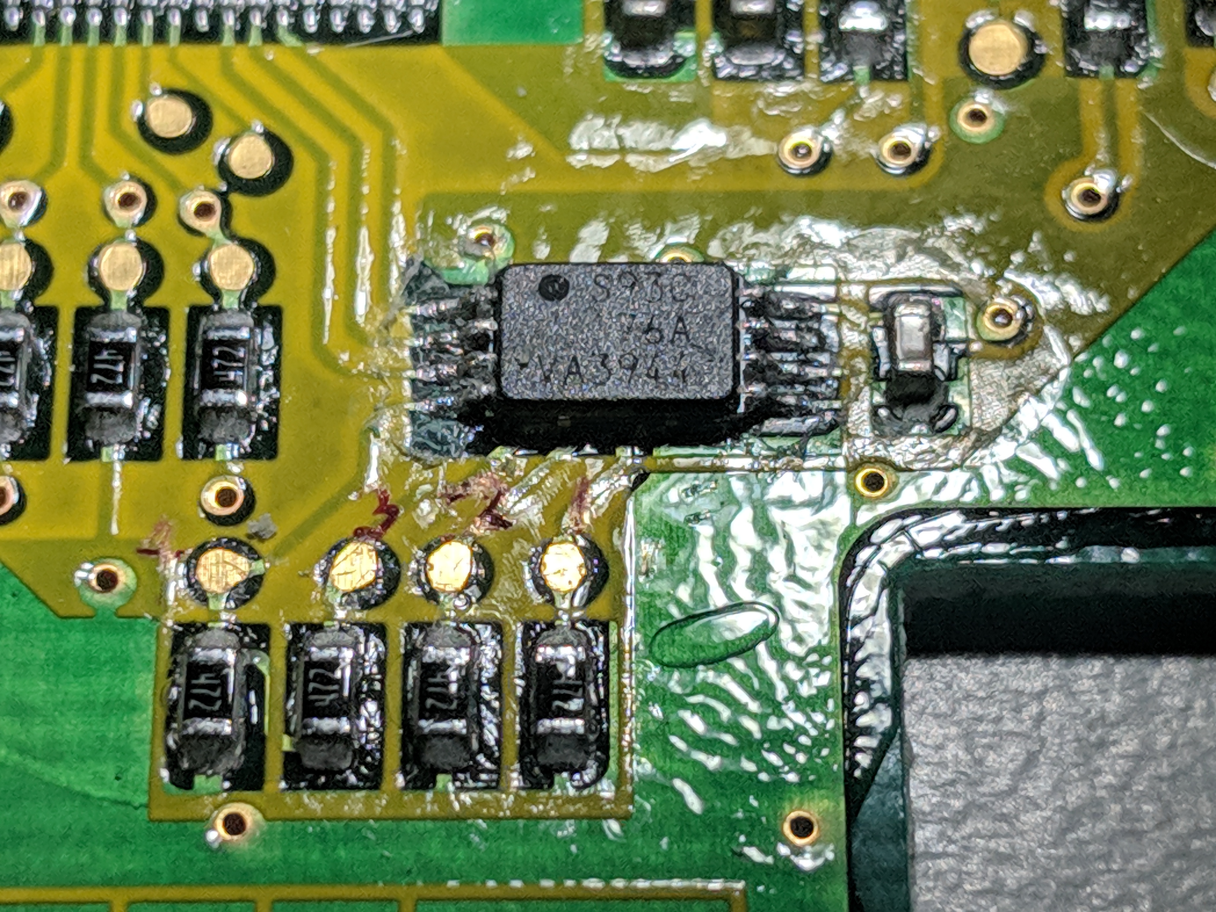


coulomb said:...
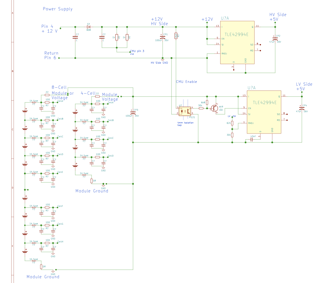
I find it strange that the lower voltage regulator has a voltage divider going to pin 1, and the upper one doesn't. Worth a double check?
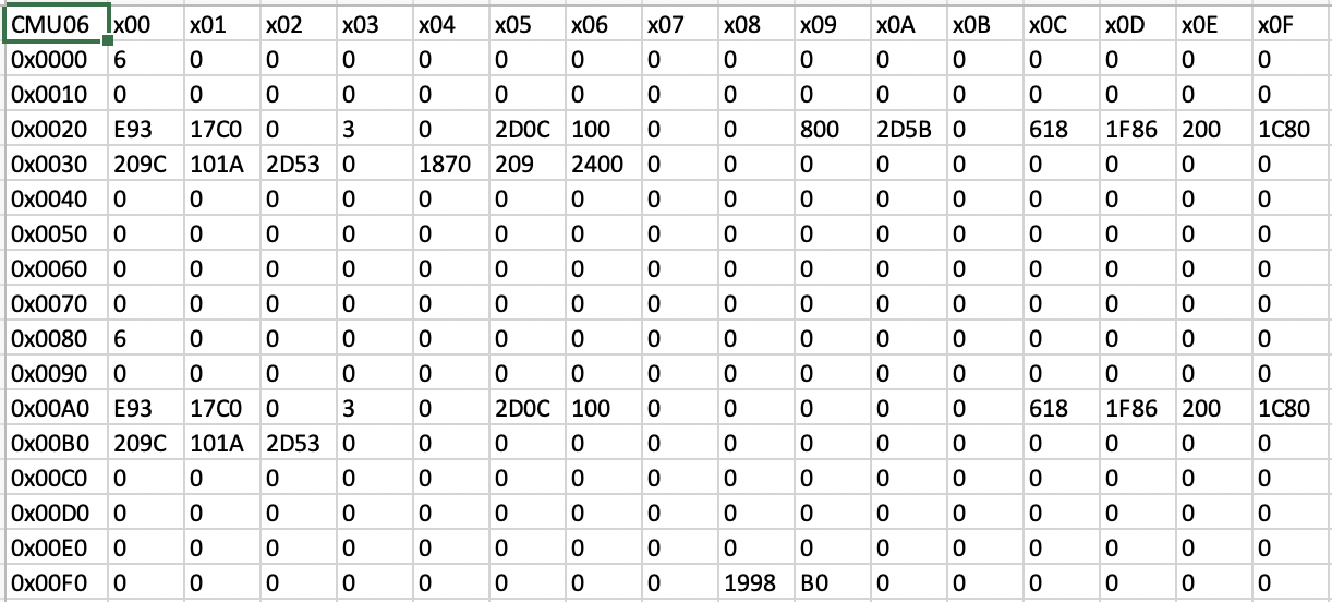
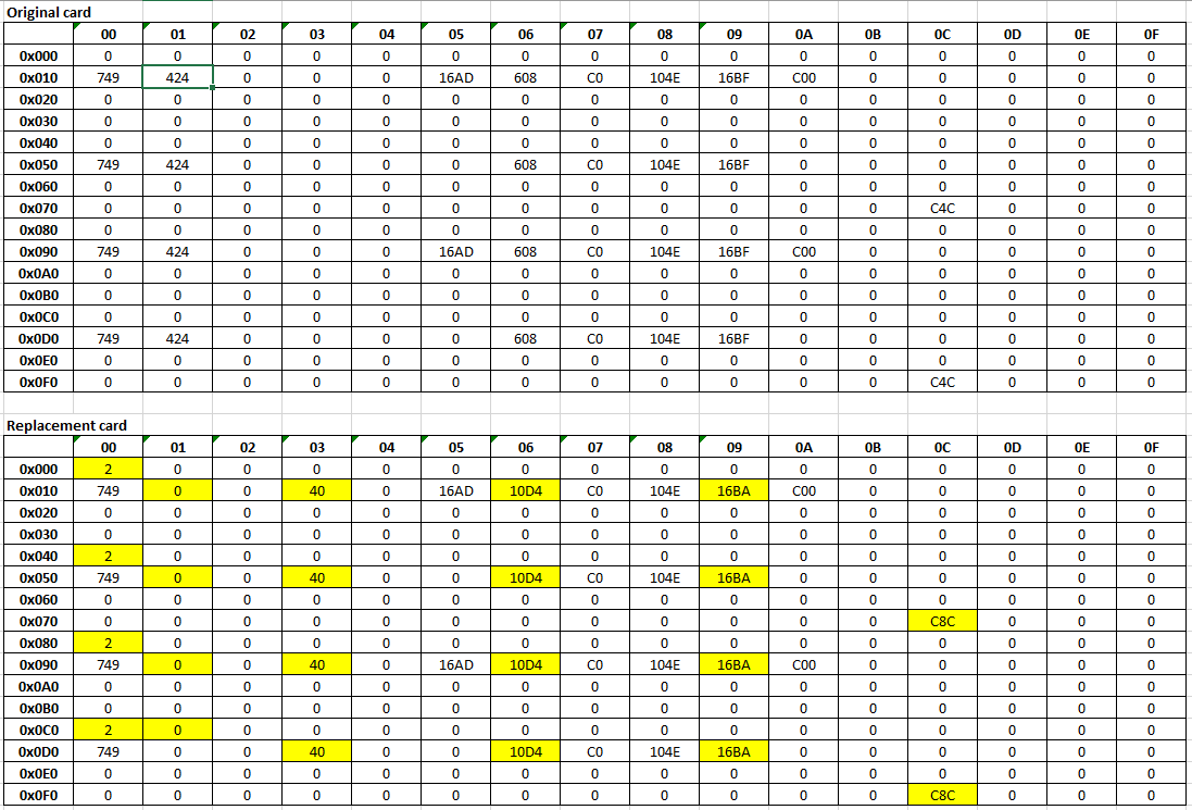
If the two 256 word banks are mirrored doesn't that suggest a problem with the most significant address bit of your reader not addressing the whole chip properly ? Remember Rupert had problems with his read attempts as well...kiev said:Here is a picture of the lower 256 words, the upper 256 were exactly identical just add 0x100 to the address in the left column.
/*
  MicrowireEEPROM Arduino Library Source File to
 Read and write a Microwire EEPROM.
 Written by Timo S <[email protected]>
 Mods by MarkGen (MG).
 notes by kiev, 10/23/2019
 This code was found on github in the public domain.
*/

#include "Arduino.h"
#include "MicrowireEEPROM.h"

// class :: member
MicrowireEEPROM::MicrowireEEPROM(int cs_pin, int clk_pin, int di_pin,
                                 int do_pin, int pg_size, int addr_width,
								 int clock_period)
{
//use the "this" pointer for current class member reference
  this->CS = cs_pin;
  this->CLK = clk_pin;
  this->DI = di_pin;
  this->DO = do_pin;

  this->ADDRWIDTH = addr_width;
  this->PAGESIZE = pg_size;
  this->HALF_CLOCK_PERIOD = clock_period / 2;

  // make CS, CLK, DI outputs
  pinMode(CS, OUTPUT);
  pinMode(CLK, OUTPUT);
  pinMode(DI, OUTPUT);

  // make DO an input
  pinMode(DO, INPUT);
}

// member function used to either send or read some data value
long MicrowireEEPROM::transmit(int data, int bits)
{
        int dout = 0; //create loop to shift bits
        for (int i=(bits-1); i>=0; i--) {
                dout |= ((int) digitalRead(DO)) << i;//read bit, typecast it,
		//then bitshift left and compound OR to get new dout integer

                if ((1 << i) & data) {
			digitalWrite(DI, HIGH);//send data
		    }
                else {
			digitalWrite(DI, LOW);
		    }

                delayMicroseconds(HALF_CLOCK_PERIOD);
                digitalWrite(CLK, HIGH);
                delayMicroseconds(HALF_CLOCK_PERIOD);
                digitalWrite(CLK, LOW);
        }
        digitalWrite(DI, LOW);
        return dout;
}

void MicrowireEEPROM::send_opcode(char op)
{
	   //------
	   //MG added to ensure CS & DI are low before
	   //making them HIGH.
	   digitalWrite(CS, LOW);
	   digitalWrite(DI, LOW);

	   //----------
	  //MG - Commented out
        //digitalWrite(CLK, HIGH);
        //delayMicroseconds(HALF_CLOCK_PERIOD);
	  //----------
        digitalWrite(CLK, LOW);
	   delayMicroseconds(HALF_CLOCK_PERIOD); //MG added to
		//ensure adequate time for CLK to go LOW
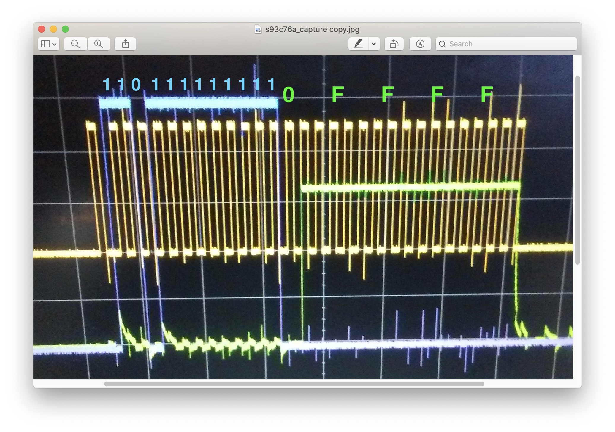
		//93LC86 Must have CS  & DI High on positive
		//edge of the clock bit

        digitalWrite(CS, HIGH);
        digitalWrite(DI, HIGH);
        // transmit start bit and two bit opcode
        transmit((1 << 2) | op, 3);
}

//class member function to read a memory address
int MicrowireEEPROM::read(int addr)
{
        send_opcode(2); //the opcode for read is 02
        transmit(addr, ADDRWIDTH); //sends the desired address
		//a leading dummy zero is returned, add extra bit holder
        long data = transmit(0, PAGESIZE+1); //return with the value
        digitalWrite(CS, LOW);
        return data;
}

void MicrowireEEPROM::writeEnable(void)
{
        send_opcode(0);
	  //---------------------------------
	  //transmit(0xFF, ADDRWIDTH);
 	  //MG - Increased 1's data from 8 bits to 16bit
	  //EEPROM 93LC86 has 11/10 bit Adress width
	  //0xFF is 0000 0000 1111 1111 results in sending
	  //leading zeros for ADW's > 8
        //0xFFFF fills all 16 bits of the INT with 1's
	  //0xFFFF = 1111 1111 1111 1111
        transmit(0xFFFF, ADDRWIDTH);
        digitalWrite(CS, LOW);
}

void MicrowireEEPROM::writeDisable(void)
{
        send_opcode(0);
        transmit(0x00, ADDRWIDTH);
        digitalWrite(CS, LOW);
}

void MicrowireEEPROM::write(int addr, int data)
{
        send_opcode(1);
        transmit(addr, ADDRWIDTH);
        transmit(data, PAGESIZE);
        digitalWrite(CS, LOW);
}/*
MicrowireEEPROM library header file
added notes, kiev 10/24/2019
*/
#ifndef MICROWIREEEPROM_H
#define MICROWIREEEPROM_H
#include "Arduino.h"
class MicrowireEEPROM {
private:
// Microwire needs four wires (apart from VCC/GND) DO,DI,CS,CLK
// configure them here, note that DO and DI are the pins of the
// EEPROM, so DI is an output of the uC, while DO is an input
int CS;
int CLK;
int DI;
int DO;
// an EEPROM can have a varying register or word size, usually 8 or 16 bits per memory word
int PAGESIZE;
// an EEPROM can have a varying address width (depending on its storage size)
int ADDRWIDTH;
// (half of) the clock period in us
int HALF_CLOCK_PERIOD;
long transmit(int data, int bits);
void send_opcode(char op);
public:
MicrowireEEPROM(int cs_pin, int clk_pin, int di_pin, int do_pin, int pg_size,
int addr_width, int clock_period);
int read(int addr);
void writeEnable(void);
void writeDisable(void);
void write(int addr, int data);
};
#endif/*
arduino sketch file
CMU_ee_reader.ino for reading
Microwire S93C76A EEPROM
kwh, 10/23/2019
This is a bit-banger routine forcing the lines as needed
to make a brute force read of the chip.
*/
#include <MicrowireEEPROM.h>
// Microwire needs four wires (apart from VCC/GND) DO,DI,CS,CLK
// configure them to pin# here, note that DO and DI are the pins of the
// EEPROM, so DI (chip input) is an output of the arduino uC, while
// DO (chip output) is an arduino input.
int CS=13; int CLK=12; int DI=7; int DO=2;
// Configure the memory word size in bits (16 or 8) called PGS in this // code, and the number of bits for the address bus called
// ADW. The speed at which the clock is run, SPD, is configured in
// microseconds.
int PGS=16; int ADW=9; int SPD=200;
// initialize the library
MicrowireEEPROM ME(CS, CLK, DI, DO, PGS, ADW, SPD);
//start the program setup and main loop functions
//setup opens serial port and sets the baud rate
//main loop reads the device
void setup() {
Serial.begin(9600);
}
void loop() {
//print headers
Serial.print("Address");
Serial.print("\t");
Serial.println("Hex Value");
Serial.println();
delay(200);
// create a loop to read each address
for (int addr=0; addr < (1<<ADW); addr++) {
// read the value
int r = ME.read(addr);
// give some debug output
Serial.print(addr, HEX);
Serial.print("\t");
Serial.println(r, HEX);
delay(100); // delay 100 msec
}
}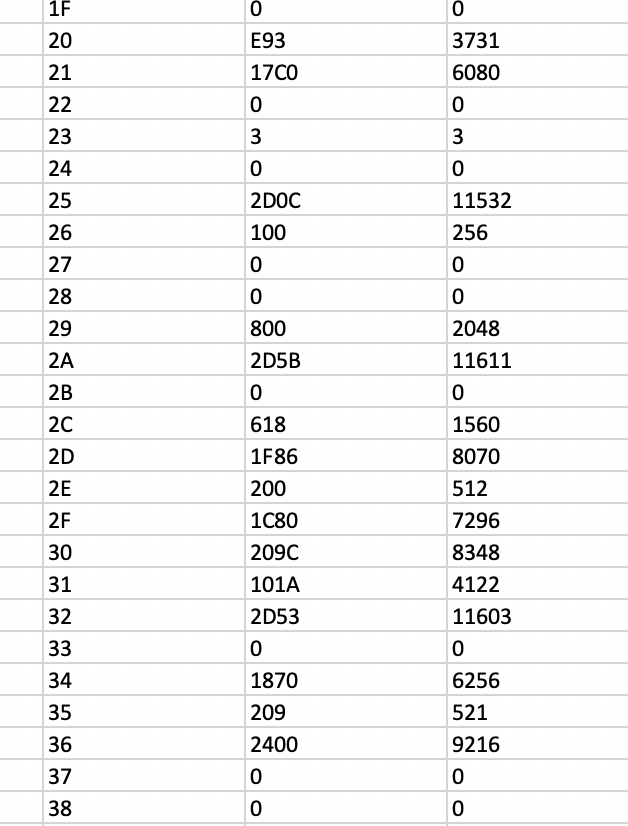
DBMandrake said:I can't imagine why they would purposefully duplicate the data in this way. And if the most significant bit was not used in the CMU board (left grounded for example) because they only needed 256 words, you would not expect to find duplicated data in the top 256 words, they should be empty or random.
Seems a little fishy to me.
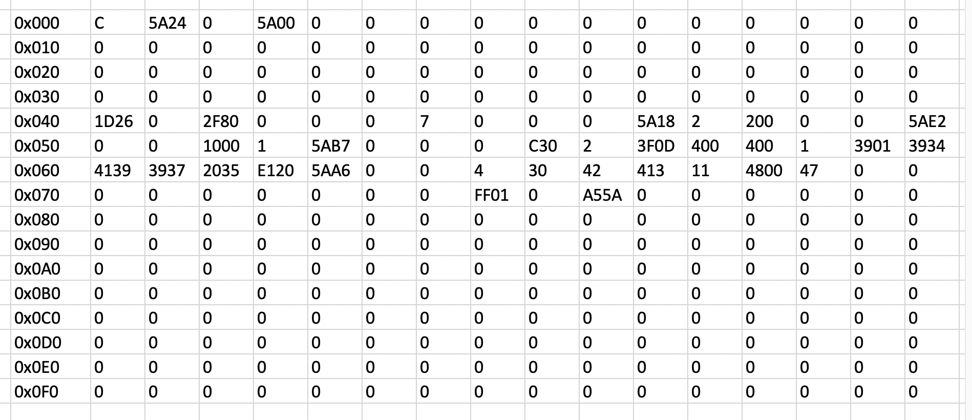
I note that if you byte swap them (i.e. process the double bytes little end first), you get "9499A795 " (two spaces at the end). That's about as close as you can get to the CMU label's number as you can get, without actually equalling itkiev said:i noticed some possible ascii text string buried in here. It doesn't look like a VIN, but looks something like a mitsubishi part number, " 9? 94 A9 97 5? Z?".
[For example, the label on BMU has part number 9499B116, and on the 8-cell CMU has 9499A794 with a serial number.]
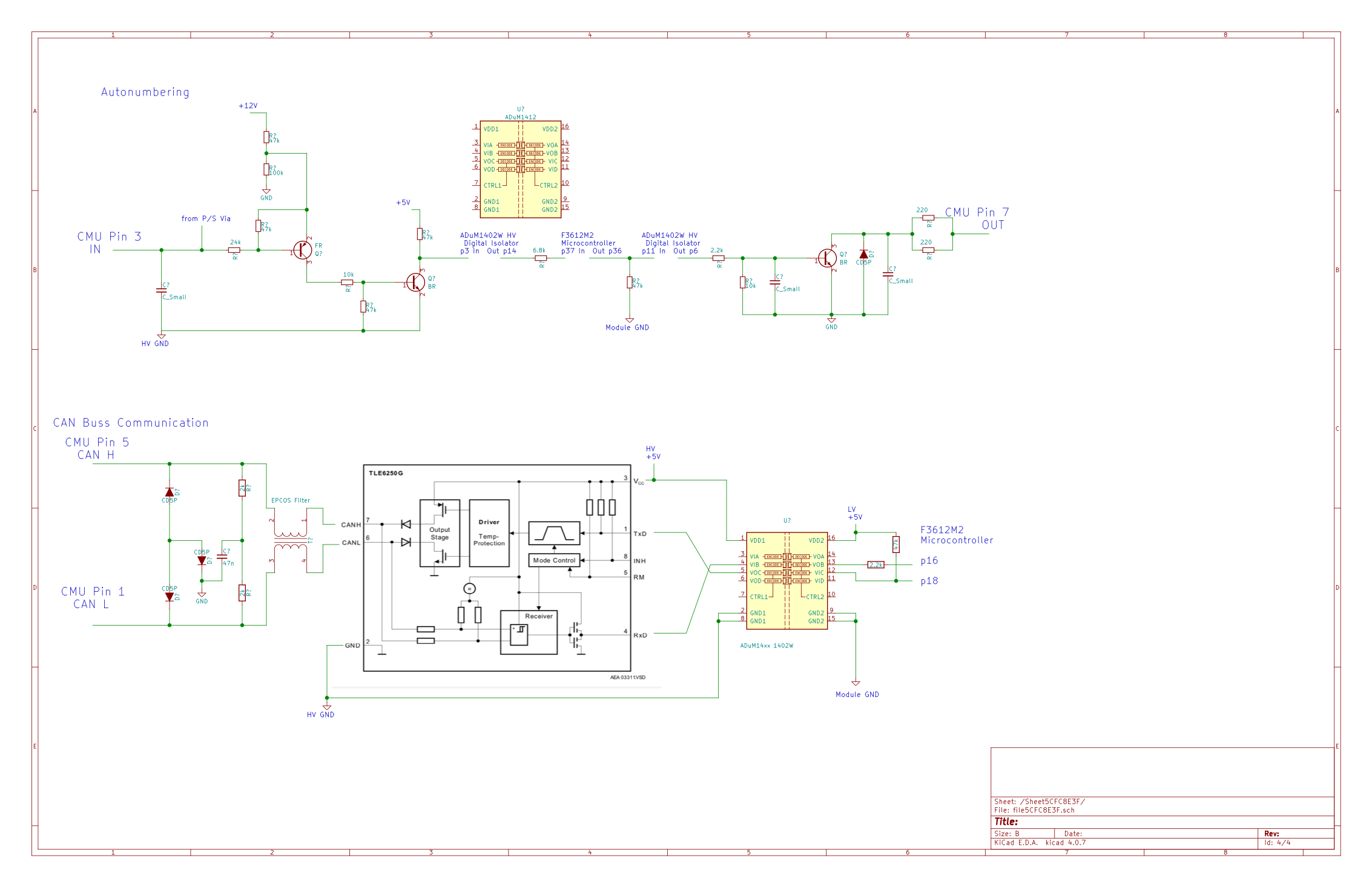
We know this statement is true as the CMU's are numbered (somehow) at the factory, however why even mention at all that the "numbering CMU ID procedure" is not necessary unless the diagnostic tool provides an option to do this ?NUMBERING CMU ID PROCEDURE
Because done at the factory, numbering the CMU ID is not necessary.
coulomb said:...
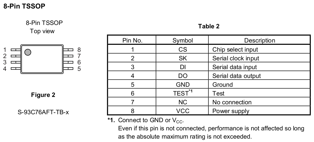
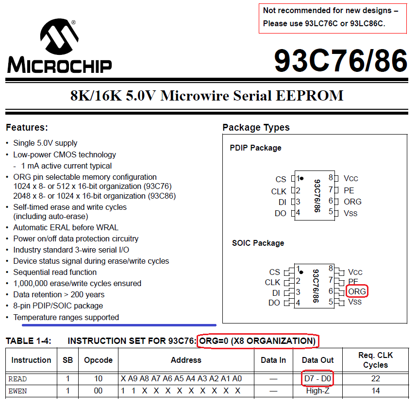
Anyone have a CMU board handy that they can test for me, please? Pin 5 is Vss (ground), pin 8 Vcc (+5V). I just want to know does pin 6 connect to Vss (pin 5) or Vcc (pin 8). Thanks in advance.
.
Yes, that's exactly what I wanted, thanks. The board I have here is also green, marked exactly the same.kiev said:On my 8-cell CMU board marked "G8D-795M-8 PWB(A) ver0.0.2", pin 6 is tied to the same ground as pin 5. The board is green in color, as i understand there are some red boards out there. HTH
Ah! That will be the problem. The first manual I found was from Microchip, and it does have the ORG pin. I guess that means we should not use Microchip parts as a replacement, and in fact we should check any manufacturer's part to see that it is suitable for this board. Or of course hack the board to pull that pin high. I just assumed that all the parts with the same part number would be directly compatible. These would hopefully be "mostly compatible", or "compatible with one condition".In the pinout on page 1 it shows pin 6 as Test and don't care about connection, so not sure about the ORG designation?
Enter your email address to join: