A
Anonymous
Guest
Hi.
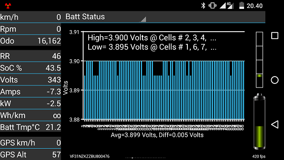
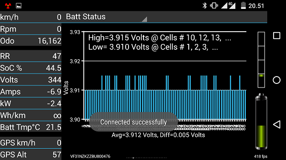
CaniOn has shown our ev charges barely 2,4kW when our ev is charging from a charging point capable of 16A 230V AC phase-neutral (Europe) which would be 3,7kW minus inverter consumption. This rate goes for all times when charging below 95% SoC or so.
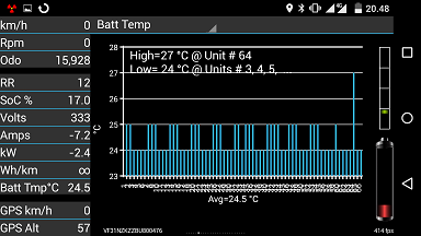
I wonder if this limit is decided by the ECU or onboard charger.
From sharings on this forum I have read the ECU charge limit to be 4kW. On a table in the section of technical articles it shows the ECU accepts up to 10A which would equal 3,6kW on the HV wires. The total draw from the AC supply would be 3,6kW plus inverter consumption.
So I wonder how to adjust so the charger provides full 10A output. Anybody who knows how this is done?
Reading an article found in the folder of technical articles about how certified technicians carries out update of the ECU using MUT3 equipment and Medic 3 computer software I'm wondering whether such equipment is accessible and whether its realistic using this to adjust the max current rate of charge. Any knowledge and experience on this anyone?
I've seeing the fuse protecting the HV wiring from the onboard charger is rate at 20A. This one is located in the MCU on the HV wires from the onboard charger.
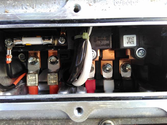
This would indicate the physical wiring being capable of handling a maximum of 20A equal to 7,2kW output at 360V.
I've got a second charger from a c-zero which I'm considering to parallel. However this would only be effective if finding a way to either
- limit either charger to max 5A each. A total of 10A output as is the current limit programmed on the ECU.
- reprogram the ecu to a higher rate.
- adjust/reprogram the onboard charger to provide more power.
- remove the current signal to the ECU (if even possible to still initiate charge)/ Adjust the signal to a value acceptable for the ECU while actually charging more within the physical limits of fuses.
So anybody with experience in dealing with reprogramming the ecu, adjusting the current signal and paralleling the onboard charger, please share.
Also does anybody know in which physical location the current measurement is done?
I know of the current sensor onboard the battery pack and wonder if the onboard charger has one as well.
Thanks.
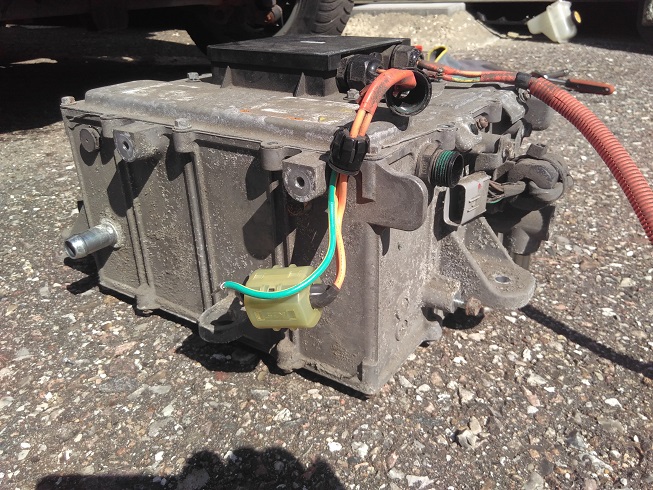
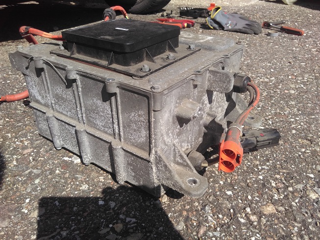
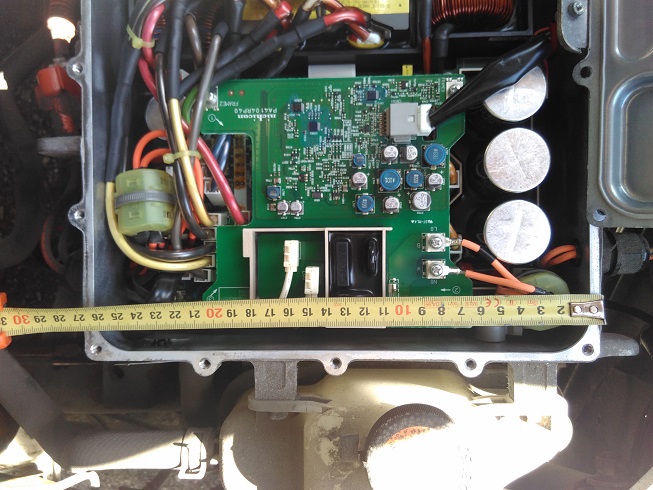
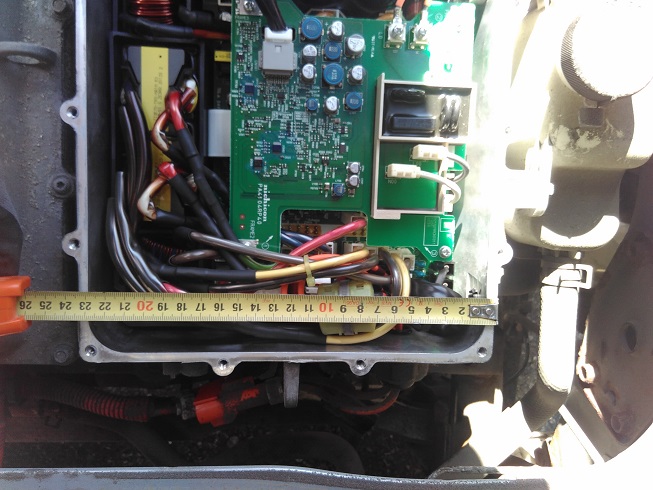
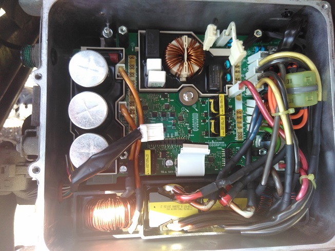
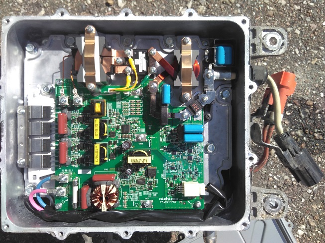
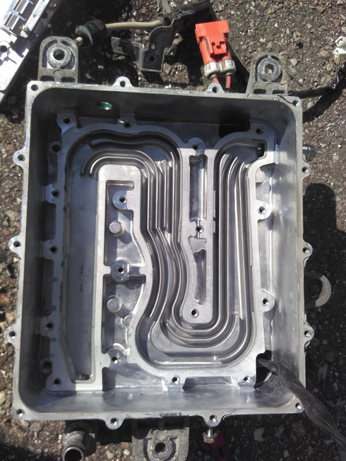
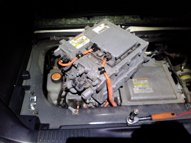
Photos of the onboard charger:
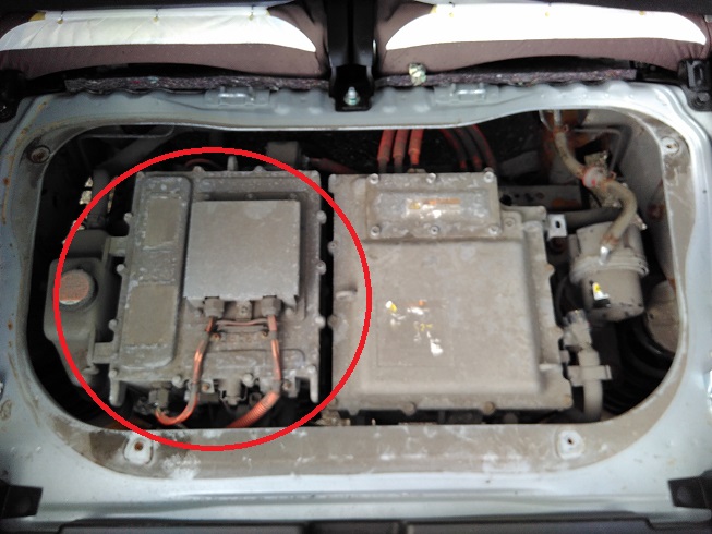
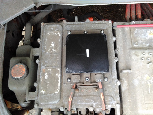
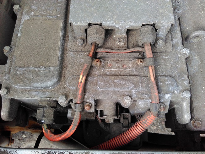
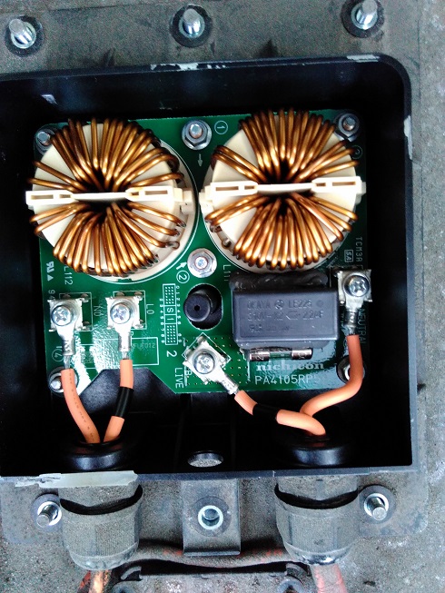
Anybody knows what this does?
And explain what the orange wire passing outside does?
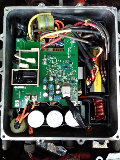
I'm noticing the AC onboard charger is placed on top of the DC/DC charger. I wonder if wanting to remove the AC charger to use in another car is this able to separate at all from the DC/DC charger?
CaniOn has shown our ev charges barely 2,4kW when our ev is charging from a charging point capable of 16A 230V AC phase-neutral (Europe) which would be 3,7kW minus inverter consumption. This rate goes for all times when charging below 95% SoC or so.

I wonder if this limit is decided by the ECU or onboard charger.
From sharings on this forum I have read the ECU charge limit to be 4kW. On a table in the section of technical articles it shows the ECU accepts up to 10A which would equal 3,6kW on the HV wires. The total draw from the AC supply would be 3,6kW plus inverter consumption.
So I wonder how to adjust so the charger provides full 10A output. Anybody who knows how this is done?
Reading an article found in the folder of technical articles about how certified technicians carries out update of the ECU using MUT3 equipment and Medic 3 computer software I'm wondering whether such equipment is accessible and whether its realistic using this to adjust the max current rate of charge. Any knowledge and experience on this anyone?
I've seeing the fuse protecting the HV wiring from the onboard charger is rate at 20A. This one is located in the MCU on the HV wires from the onboard charger.

This would indicate the physical wiring being capable of handling a maximum of 20A equal to 7,2kW output at 360V.
I've got a second charger from a c-zero which I'm considering to parallel. However this would only be effective if finding a way to either
- limit either charger to max 5A each. A total of 10A output as is the current limit programmed on the ECU.
- reprogram the ecu to a higher rate.
- adjust/reprogram the onboard charger to provide more power.
- remove the current signal to the ECU (if even possible to still initiate charge)/ Adjust the signal to a value acceptable for the ECU while actually charging more within the physical limits of fuses.
So anybody with experience in dealing with reprogramming the ecu, adjusting the current signal and paralleling the onboard charger, please share.
Also does anybody know in which physical location the current measurement is done?
I know of the current sensor onboard the battery pack and wonder if the onboard charger has one as well.
Thanks.
Photos of the onboard charger:


Anybody knows what this does?
And explain what the orange wire passing outside does?

I'm noticing the AC onboard charger is placed on top of the DC/DC charger. I wonder if wanting to remove the AC charger to use in another car is this able to separate at all from the DC/DC charger?


