No READY. P1A15 error. Condenser charge timeout.

Mitsubishi i-MiEV Forum

Help Support Mitsubishi i-MiEV Forum:

This site may earn a commission from merchant affiliate links, including eBay, Amazon, and others.
kiev said:
For this entire thread i have created an INDEX post on page 1, post #4.
Thanks for doing that, Kiev.

The last link for the isolation board didn't seem to work for me. Edit: This may be the link you wanted:
https://myimiev.com/forum/viewtopic.php?p=43738#p43738

Edit 2: Huh! My link doesn't seem to work either. Must be a gremlin on that page. Perhaps mention that it's the last post on page 43 (at least for my Chrome browser). The post before the one these links leads to (on the end of the page before). Hopefully a site re-index will fix this.
 
Good catch on that, thanks for checking. That link behaves weirdly for me too.
[edit]
Went back to look and it appears to be working now. The post # is a few numbers greater than the one you listed.
 
Hi Greg I have same problem on 2011 Peugeot ion.are you able to supply circuit board and wiring diagram for AD202KN MOD
 
GregFordyce said:
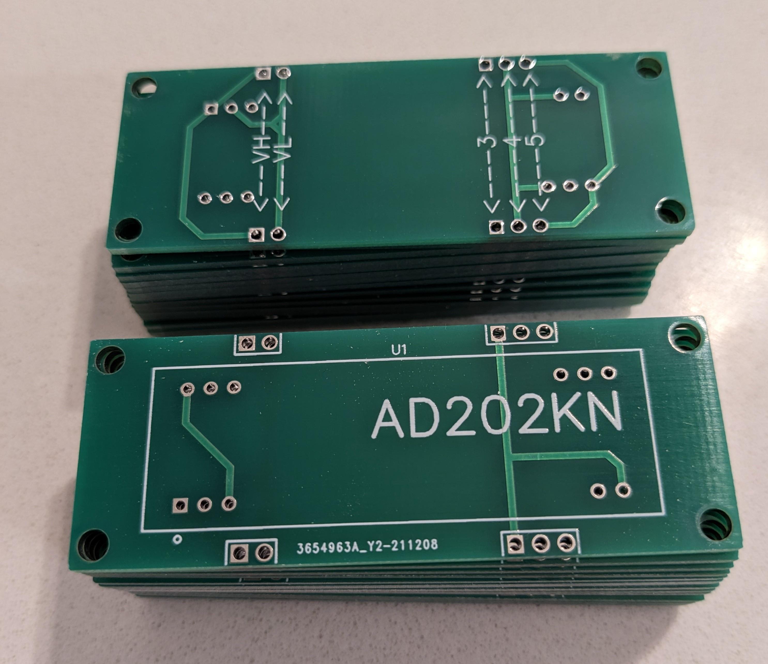
I've got some more of the AD202KN PCBs from China. If anyone requires one, message me with name and address and I'll send a PayPal invoice. Cost is £7 to UK and £8 everywhere else.

Greg

JgZIMYr.jpg

This means he wants you to use the Private Message feature to contact him about this. click on his name above and the option to send a private message should show up.
 
H All,

I have the P1A15 error which is still only occasional but worsening.

I am wondering if (without reading the entire thread) there is write up somewhere to fault-find this issue logically from start to finish to see if my issue lies with the 'hybrid board' (if I understand things at all) or somewhere else?

I have a fair amount of experience with these cars and a cloned MUT3.

Regards, Martin
Isle of Colonsay
Scotland
 
Hi Kiev,

Thank you for your reply (I saw the reference to the index somewhere in the thread but it didn't work - probably just me).

So, it seems the most reliable way to determine if my instance of the P1A15 issue is to determine the behaviour of the voltage on the relevant 'condenser'. I see drcat has a whizo diagnostic tool that has a 'scope function (if I understand correctly). This is not something I have yet come across on my clone MUT3 (but that does not mean it isn't there). Is using the MUT3 (somehow) going to tell me what the voltage is doing at the condenser? If not, I have a reasonable 'scope (a Hantek DSO507P). Can someone tell me where I need to put the probes to do it the hard way?

Regards, Martin.
 
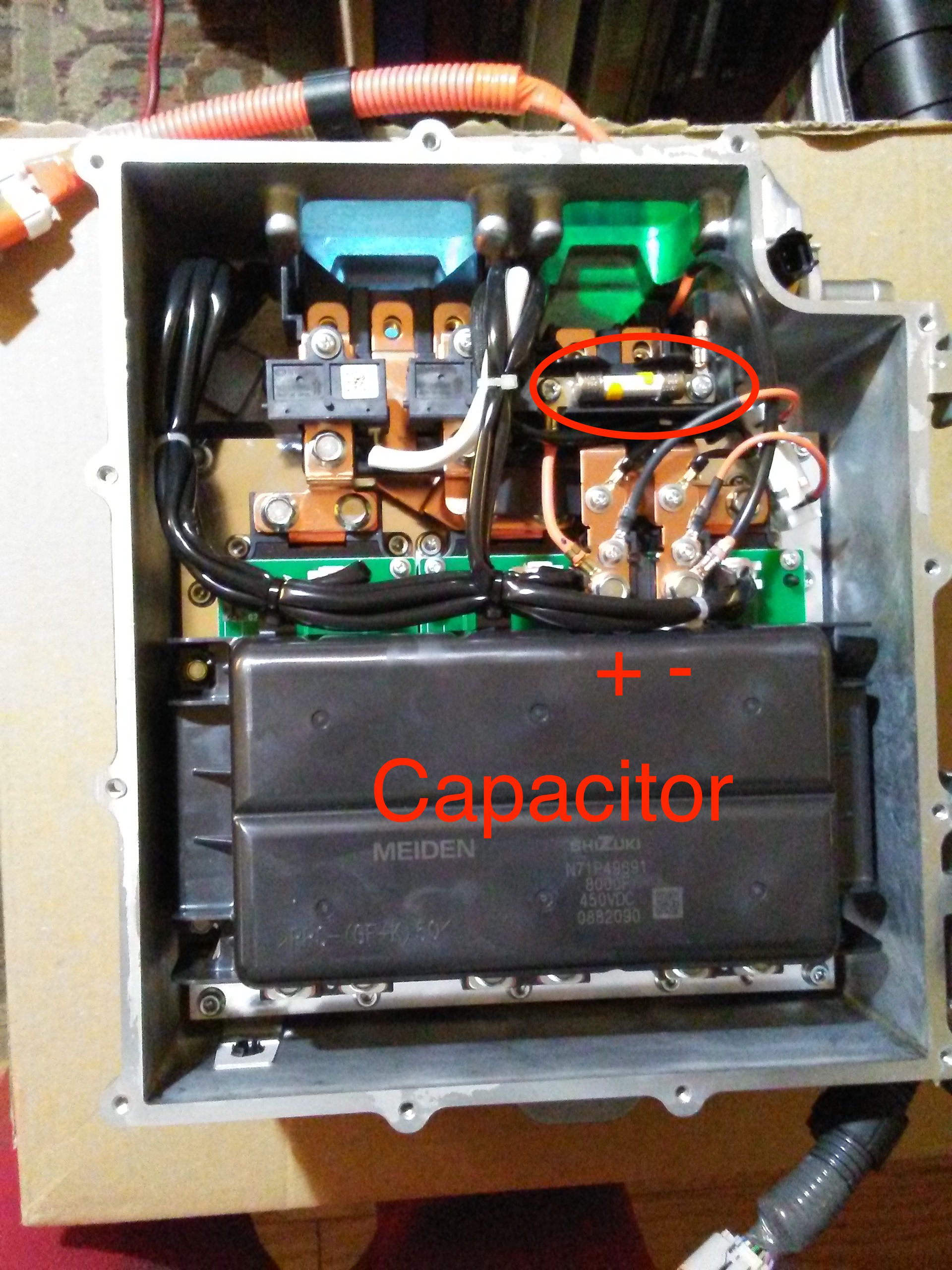
Here is a picture of the MCU with the entire cover off. But you can access the HV lines thru the little cover. Check it with a voltmeter first to get happy with the polarity and attach points, then set your scope trigger and capture the precharge.
tEh7pHq.jpg


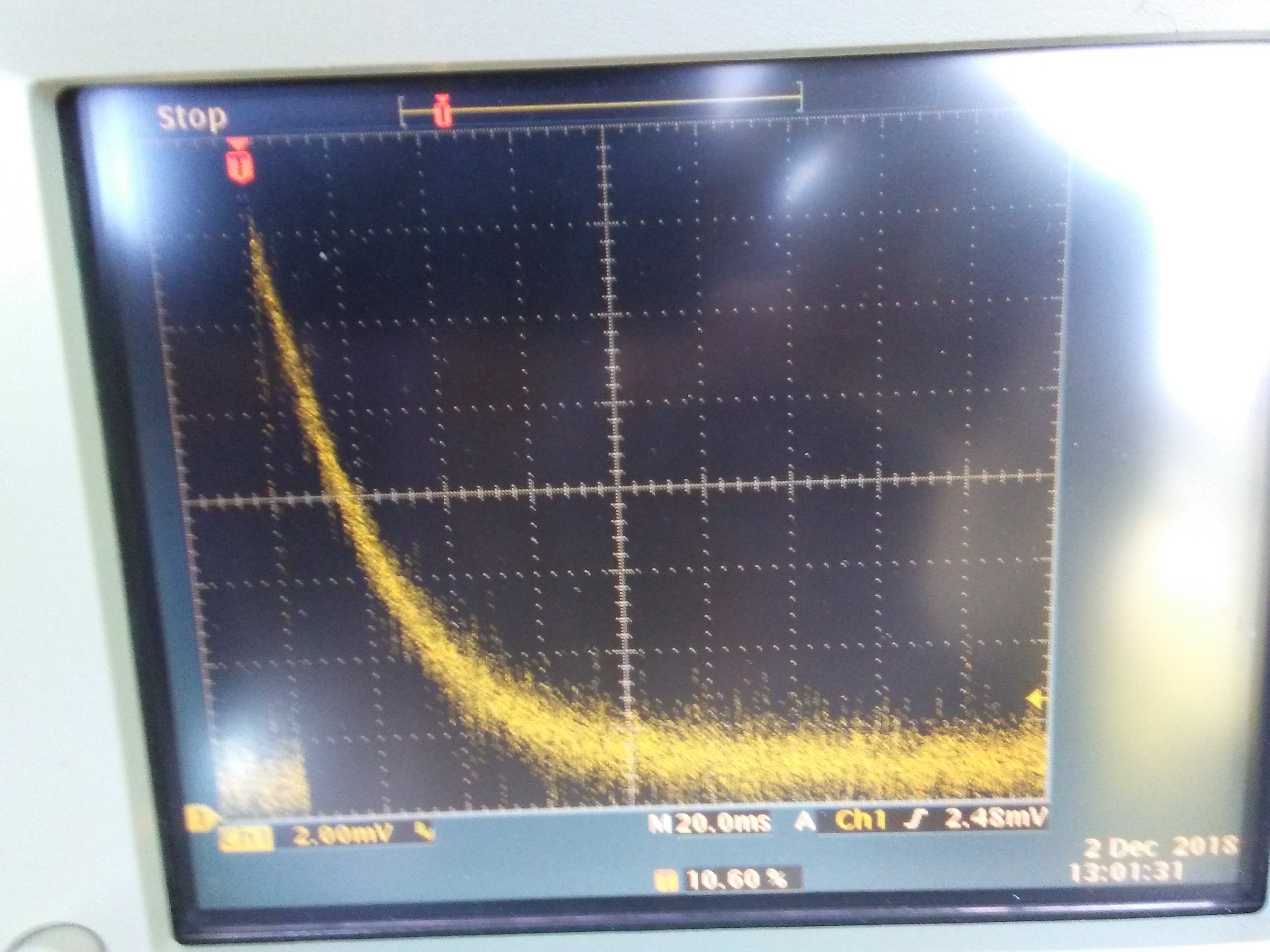
You will likely want to look at the voltage waveform, but here's a precharge capture i made with a current probe on the scope,
x6ViCfV.jpg


i think some of the scan tools have a feature to display live data and can produce a graph of the HV to the MCU also, but i don't own one that does.
 
Thanks KiEV - I'll give it a go!

Given that my i-MiEV is apparently only in the early stages of this problem and the car starts more often than not, will it be obvious from the 'scope trace that the voltage is sagging below what it should be (confirming the diagnosis) even though the Ready light may come on?
 
That's the way mine was and it slowly got worse until no longer would start. Being that it is intermittent will be difficult to capture, very frustrating for sure.
 
My Ion with the P1A15 fault now won't start at all.

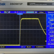
I'm about to remove the controller to do the 2MR resistor fix and this is what my Hantek scope tells me peak capacitor voltage is 348V and although I don't know what the pack voltage actually is, I think it's wrth a try to do the 2MR resistor fix:

8xb7Z89


MW
 
Your scope is working good, that is a nice capture trace.


Some folks have had luck with changing the gain by adding a resistor; some have done the task without removing the MCU.

348 VDC is likely the pack voltage, but the value read by the controller/EV-ECU thru the hybrid circuit may be something less and that is causing the P1A15 DTC fault.
 
Hi KiEV,

I thnk I may have misunderstood, then, as I thought the scope probes should be put across the capacitor terminals in order to establish if the hybrid board is at fault or not...? Anyway, the inverter is out, now and I'm about to access the bottom plenum to effect the 2MR resistor 'bodge'...
 
Maybe i misunderstood too, see if this helps.

The scope gives you the actual voltage at the terminals (the true voltage); then the MUT or some scan tool can be used to read from the data items list to give you the voltage value that the EV-ECU or MCU measured and "thinks" is the truth. It seems that the error code will be thrown if there is a difference of more than 6 or 8 volts between the two.

The "true" value or reference pack voltage for the car is determined by the BMU from the sum of the readings of cell voltages by the CMUs in the pack.
 
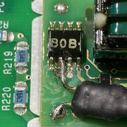
OK. Understood. So, I assume (if I could get at it) I could measure what the car is 'seeing' by attaching the scope probes somewhere else in the inverter - the hybrid PCB? If so, I am wondering if having now added the 2MR resistance to my hybrid board, I could test it on the bench to see if the fix works before putting the inverter back into the car (I have a 400VDV bench power supply)?

MW
 
Yes you can bench test it. Don't use a 400V supply; the hybrid supply is 15V but it will run on 12, and the input voltage at the hybrid terminals is less than 5V (e.g. can use 3 AAA batteries in series as the signal to be measured).


Take a look at the Index post on page 1, post #4, to get information about this problem.
 
Back
Top