Gen1 DCDC Converter Troubleshooting and Repair

Mitsubishi i-MiEV Forum

Help Support Mitsubishi i-MiEV Forum:

This site may earn a commission from merchant affiliate links, including eBay, Amazon, and others.
The thermistor may be the culprit. That is reading way too low at least compared to mine. You could hook up the ohmmeter to just the thermistor, then use a hair dryer to add heat to the sensor and see if the resistance changes.
 
eldenh said:
1.3k across the thermistor. 4.74v at TP217. Pin 12 of IC206 is 4.94v.

One leg of the photocoupler is 0v, and the other leg is also with 240v. With 303v the other leg goes to almost 5v.

Good progress.
With 303V opamps are happy and the photocoupler is turned OFF, that's why the leg goes toward 5V. That should cause pin 10 of the IC206 to go Low, unless there is something else in that circuit that i haven't discovered.
 
It is still being driven from some path; i will look at this again in detail.

My thermistor readings, it is NTC meaning negative temperature coefficient, resistance goes down as the temperature goes up.

Immersed in glass of ice water, temp 38 F, 420kΩ

Room temperature, 68 F, 117 kΩ

touching tip of soldering iron, ~308 F, 0.5kΩ

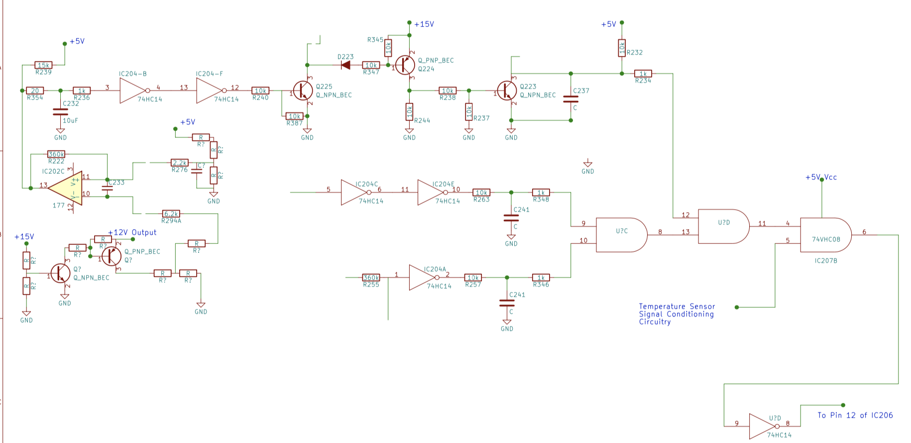
If yours is measuring around 1kΩ or so, then that is read by the [comparator]op amp as a HOT unit, and would likely send a signal to shut down the converter. But since you said pins 9 and 10 are both Low, then the shutdown is not coming from the temperature sensor, at least from that path.

if pin 9 and 10 of IC206 are Low, then pin 8 should be low-- that is driving the Q203.

Is pin 8 of IC206 Hi (~5V)? If 9 and 10 are low, but 8 is high, then it is a defective chip.
 
95k should be good. So what else is causing pin 12 to go Hi?

If 9 is high, then either 12 or 13 would be high also. If there is 5[ or 3.3 ] volts on the white wire to pin 1 of CN201, then 13 should be pulled Low; that leaves 12--and 12 comes from the temperature sensor plus the TP201 voltage, the 12V Output voltage, and ?

Sorry to be changing my mind again, i'm blaming this on the time change--There does need to be a signal on DCSW to drive the base of Q234 which will pull 13 Low
 
kiev said:
Sorry to be changing my mind again, i'm blaming this on the time change--There does need to be a signal on DCSW to drive the base of Q234 which will pull 13 Low
Yes! But note the zener diode directly from the DCSW white wire to chassis; 3.3 V should be plenty to turn on the transistor Q234 and pull pin 13 of the OR gate low. That might finally allow the soft start to happen.

Because leaving DCSW open circuit acts the same as a low signal, I'm willing to call it an active high start signal, looking for something like +3.3 V to start the DC-DC converter.
 
That is what I observe: when the white wire is open circuit there is a HI on pin 13, and when there is almost 3v on that wire pin 13 goes to 0v.
 
That's what we want, a Low on pin 13. Now to get a Low on Pin 12...

Pin 12 is fed from the inverted output of an AND gate, so both inputs must be Hi. One side is from an [Comparator]op amp reading the temperature sensor, and with TP217 reading as you measured, then that half is good. i just haven't had time to sort thru all the traces for the other half of the AND gate.

So i've spent several hours this evening scraping off the coating and tracing back and forth with all the tiny vias and traces, and i'm still not close to finding any real signal yet, it's never ending gates. The one half- AND gate has split into 4 more AND gates, so it's going to take quite a bit of time to ring this out. i've got to give my eyes a rest.
 
It looks like much of that signal processing is on the bottom side of the board, but it seems that the inputs are from the top side. Is it possible to probe the status of the inputs from the top?
 
It might be possible once we figure out the circuits. It took a long time to figure out the OBC and even still the control board is not fully traced out and i have no idea about the microcontroller code. The control board is similar to the LV section of the DCDC with the tiny vias.

All those little 2-via pads with the tiny 0.01" holes seem to be carrying signals, versus the larger diameter vias carry voltage or ground. There is no reference designation on the vias and they move the signal from the top layer to the bottom layer, sometimes they are hidden underneath a chip, and it is difficult to keep track when flipping the board over back and forth, and then trying to sketch the circuit at the same time.

Plus the clearcoat removal is tedious and time consuming--it causes many false readings if not removed.

The top layer seems to have 5 main traces from the PWM chip back to the LV section, and the bottom layer has 4 or 5 that do the same. These are likely the most important for control and that is where i am focused to determine their function. Of those lines i think we know what 3 of them do based upon your measurements.

TR104 provides a TR103-current sense signal to the PWM on pin 9 labelled as Current Limit (ILim).
 
When you were doing these tests and measurements, did you have a 12V battery connected to the Output of the 125A fuse?

Here is a sketch of a circuit which provides the command signal to pin 1 of the PWM chip IC201. It seems to combine a sense of the input and output 12V of the aux, the 15V of TP201, and the output current for charging the aux battery. Probably not an issue here for you unless you had no aux connected.

NzRsI6P.jpg
 
I had 12v hooked to the output when I first set it up for testing, but not on subsequent days. I just tested it again with 12v on the output and pin 8 of IC201 is still being held low. Pin 12 of IC206 is high.
 
Okay thanks for checking with the 12V connected.

i will sketch up what i have traced for the pin 12 gate later today; part of it is related to the temperature sensor that ends up driving pin 5 of IC207, and something else is driving pin 4 but i can't find what else is being "sensed".

Here's a draft schematic that might give you an idea of how the circuit seems to ramble on. And this is just for the feed to pin 12 of the OR gate, and it still needs work.

[edit] updated drawing
wcslaLN.png
 
Thanks Mike, it always helps to get your review and analysis, hopefully it will make sense before too long.

@ elden, when you have made your tests, was the board fully mounted into the OBC housing with all 7 of the hold-down screws? The reason i ask is that there are some Grounds traces on the board that will be floating unless the screw makes the connection thru the housing; actually it is only screws 1-3 and 5 that are used like this and would need to be mounted, screws 4,6,7 have no connection. And then the housing would need to be connected to the negative terminal of the 12V aux battery. A floating ground could be causing the PWM not to start.
 
Thanks for the hard work! I'll try to see what I can find in that shortly. I mounted the board with the 4 screws that have metal pads assuming them to be important, but have omitted #s 4, 6, 7 expecting to have to remove the board to replace whatever had failed.

Trying to troubleshoot from your pencil sketches has been rather difficult because my eyes have trouble distinguishing the pencil lines from a grayish background. I choose to build a spreadsheet to help me find where I can try to probe with the board mounted. In doing so I found that Q219 is listed as "KN" and "G16". I can't make out the label in the underside photo, so don't know which is right.
 
Back
Top