Car not charging,..DC/DC converter failure. not what we expected.

Mitsubishi i-MiEV Forum

Help Support Mitsubishi i-MiEV Forum:

This site may earn a commission from merchant affiliate links, including eBay, Amazon, and others.

electronpusher

Well-known member
Joined
Jun 25, 2017
Messages
45
Ok, well there's your problem.

Anyway, strap in, this is going to be long.

So to begin with about a month and a half ago we went to go to the shops in our iMiEV and as we turned out of our street, we noted that the car had not charged fully, and that we had the red 12v battery warning light as well as the orange exclamation mark high voltage warning light. Hmm, thats weird, so we went back home, and did some troubleshooting. We first plugged it back in, and it did not charge, we then tried our charger from our Outlander, and still no dice. Hmm, ok. We then checked the battery, all good, but it did not appear to be charging when the car was on. Hmmm.

We then tried to get the error codes from the car, and Mitsubishi said, "yeah, nah, you cannot do that". We tried different software and hardware, but nothing would allow us to read the error codes. Hmmm, ok, guess we will need to take it to the local dealer to get the codes, as they seam to be proprietary, which is very annoying, error codes should be available to the owner, but nup, Mitsubishi ain't got time for that.

Ok, we went to the dealers, I told them the symptoms and the research we had done. I told them that based on the symptoms we think the issue is the DC/DC converter as other iMiEV owners with the same symptoms found the issue was the DC/DC converter. I asked them to get the error codes for us, at our cost of course. Two days later, after they said they were having difficulty working out what was wrong, they said that the issue is the Battery ECU, and that it costs $1300AUD to replace it. We knew that the DC/DC converter had a cost in the vicinity of $4000AUD, as we were pleasantly surprised that it was going to cost only $1300AUD. I asked them if they were sure that that was the problem, and I was assured it was, so we agreed to have the Battery ECU replaced.

Well, no ETA was given, and we expected it would be a few weeks. After a few weeks we went to the dealer, and they said that they were originally going to get the Battery ECU in August 2018, but now will have it on June 6th. Phew, August would have sucked. I still have a gut feel that it was the DC/DC converter, but without the benefit of diagnostics from the MUT III, it was hard to argue with them.

So this past Friday we went to see how things were going, only to find out that they have the Battery ECU, have replaced it, and it did not fix the issue. They now believe the issue is the DC/DC converter. Well **** me, I told them that in the beginning. We argued that we should not have to pay for the Battery ECU, but they refused to accept responsibility. I then said to take the Battery ECU out, and put in the original one. "Oh, that will cost you 5 hours of labour at $170AUD an our ($850AUD) and it won't be ready until next week sometime". Fuming, we said to leave the ECU in, we'll pay for it, but we want the error codes and the original part.

We took the car home this morning, and began the investigation ourselves.

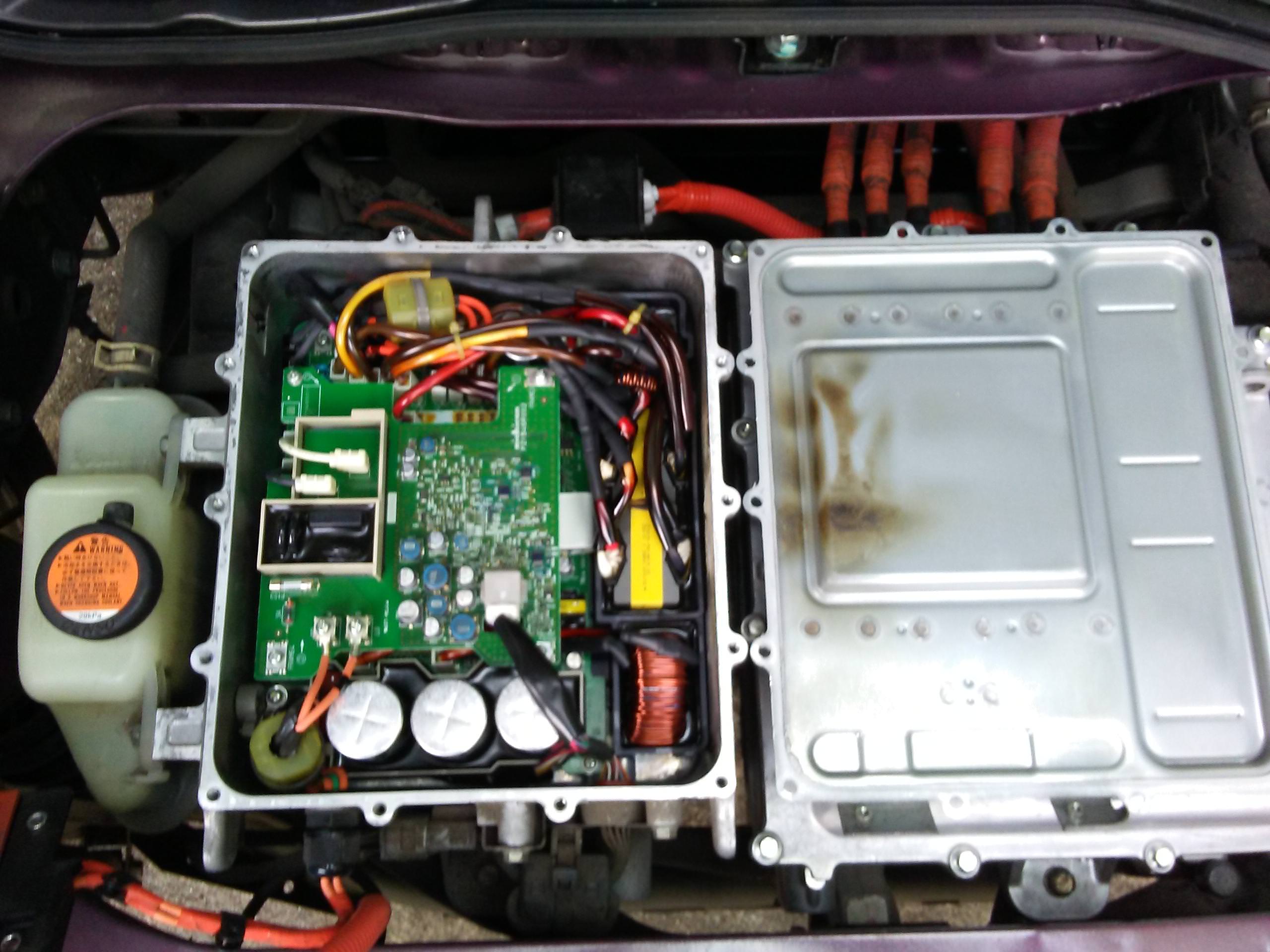
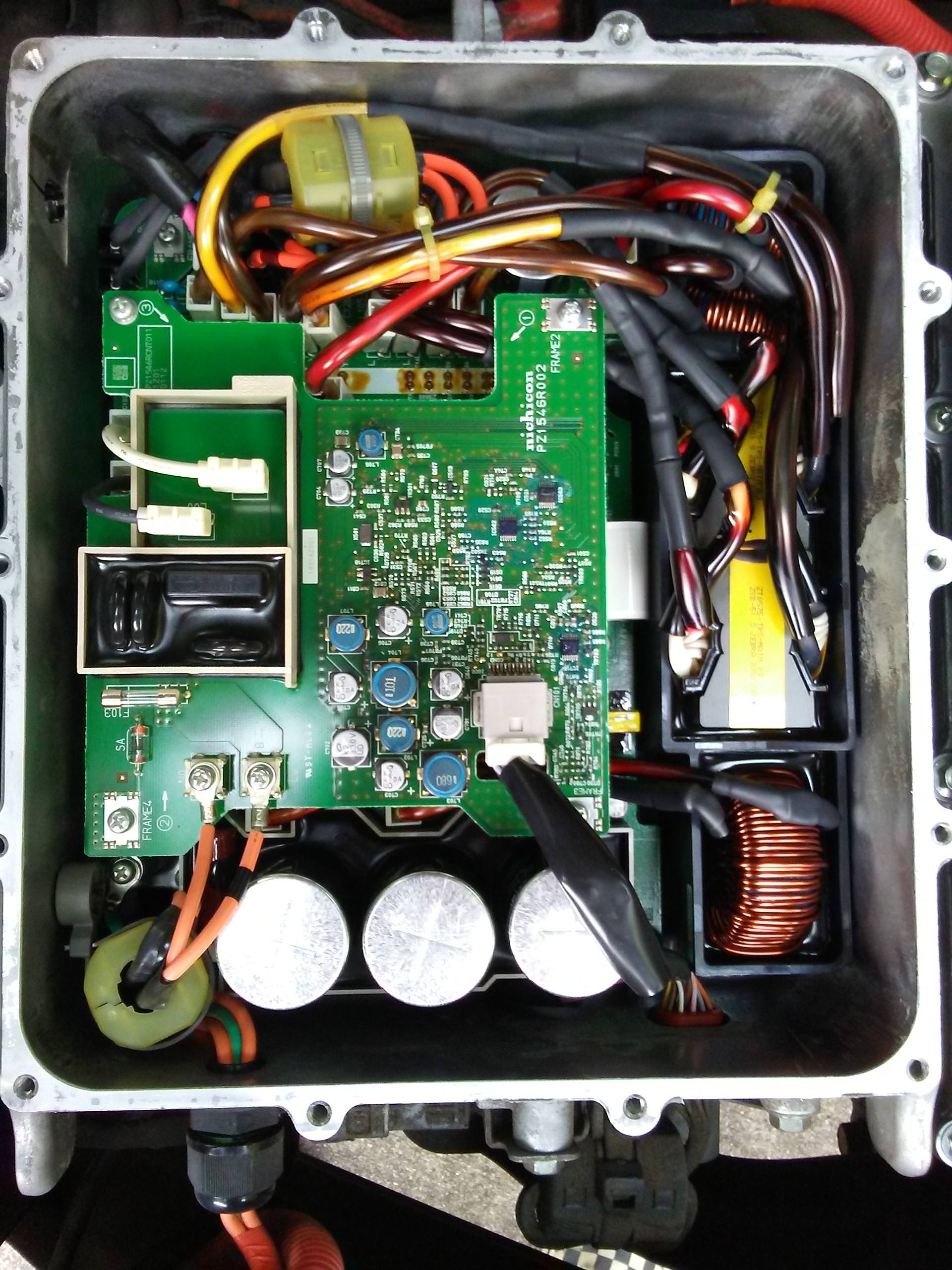
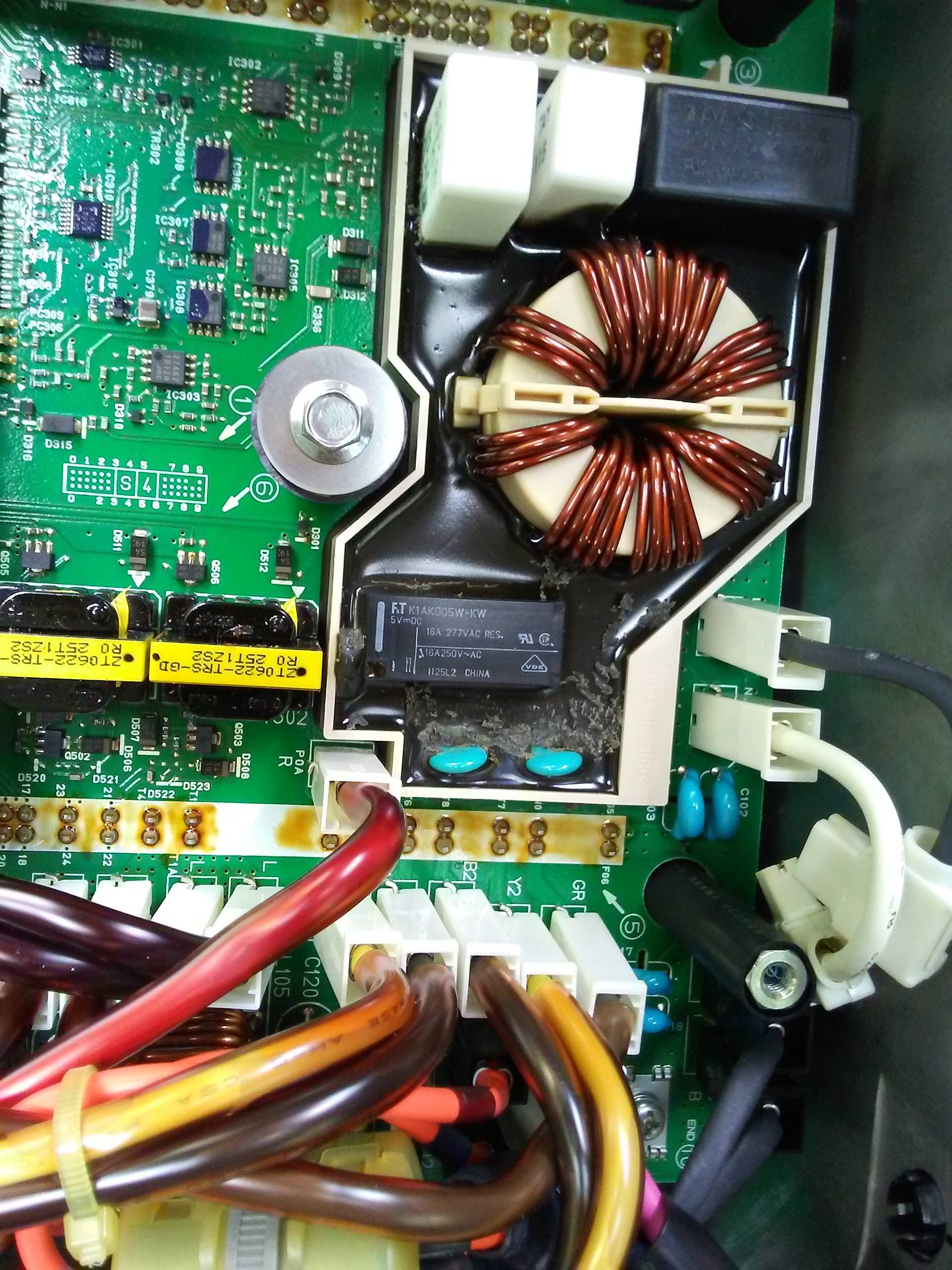
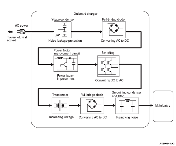
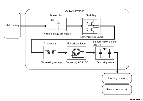
So we made the car High Voltage safe, and removed the cover of the DC/DC converter. The DC/DC converter contains two boards, the top one I believe is the AC charger input, while the bottom one is the DC/DC converter. The AC charger connects to the DC/DC converter, where the DC is converted to 330v (?) for the traction battery, and 12v for the axillary battery. The top board looked ok, and both fuses on the top board were intact, and checked with a multimeter.

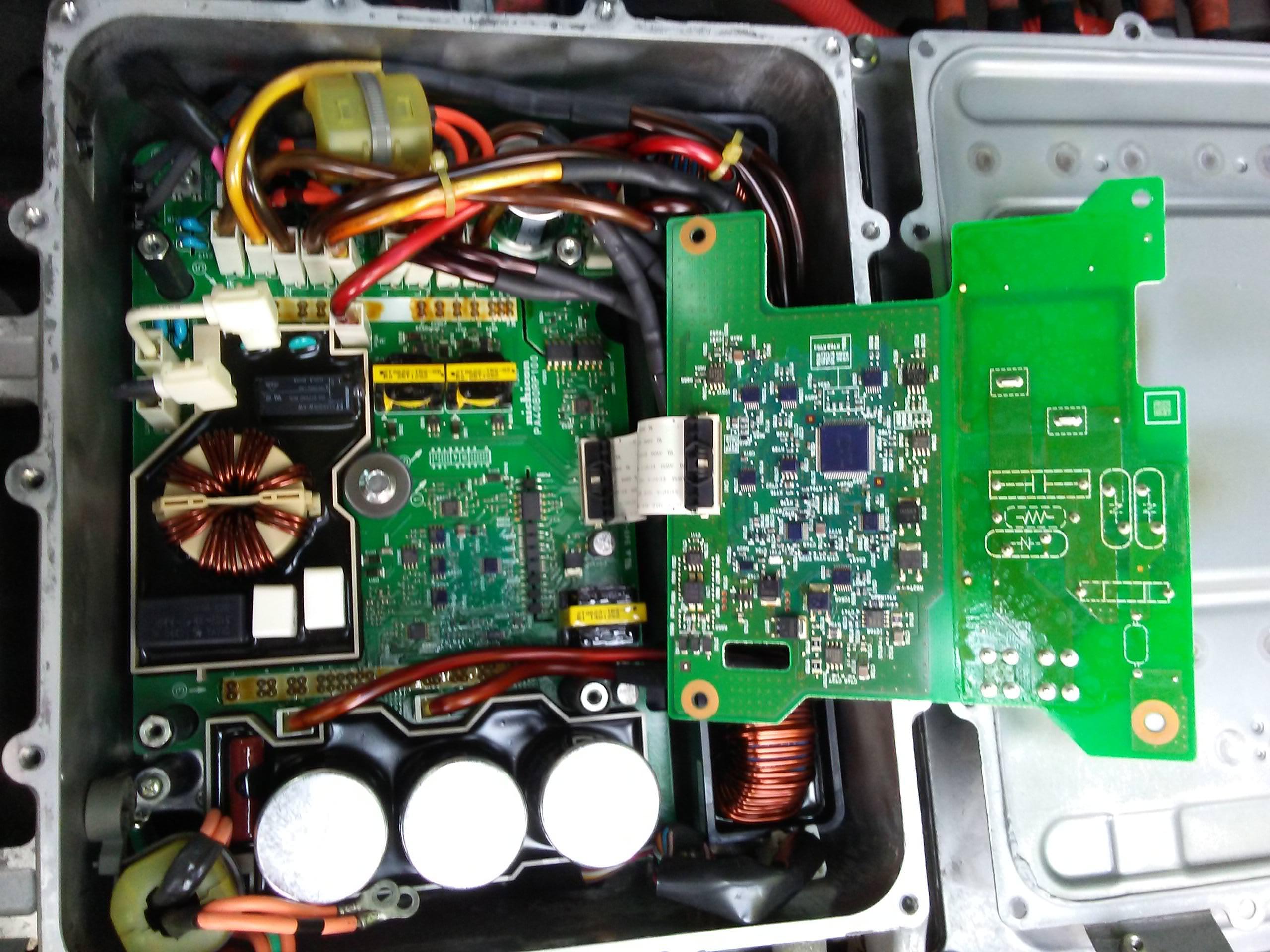
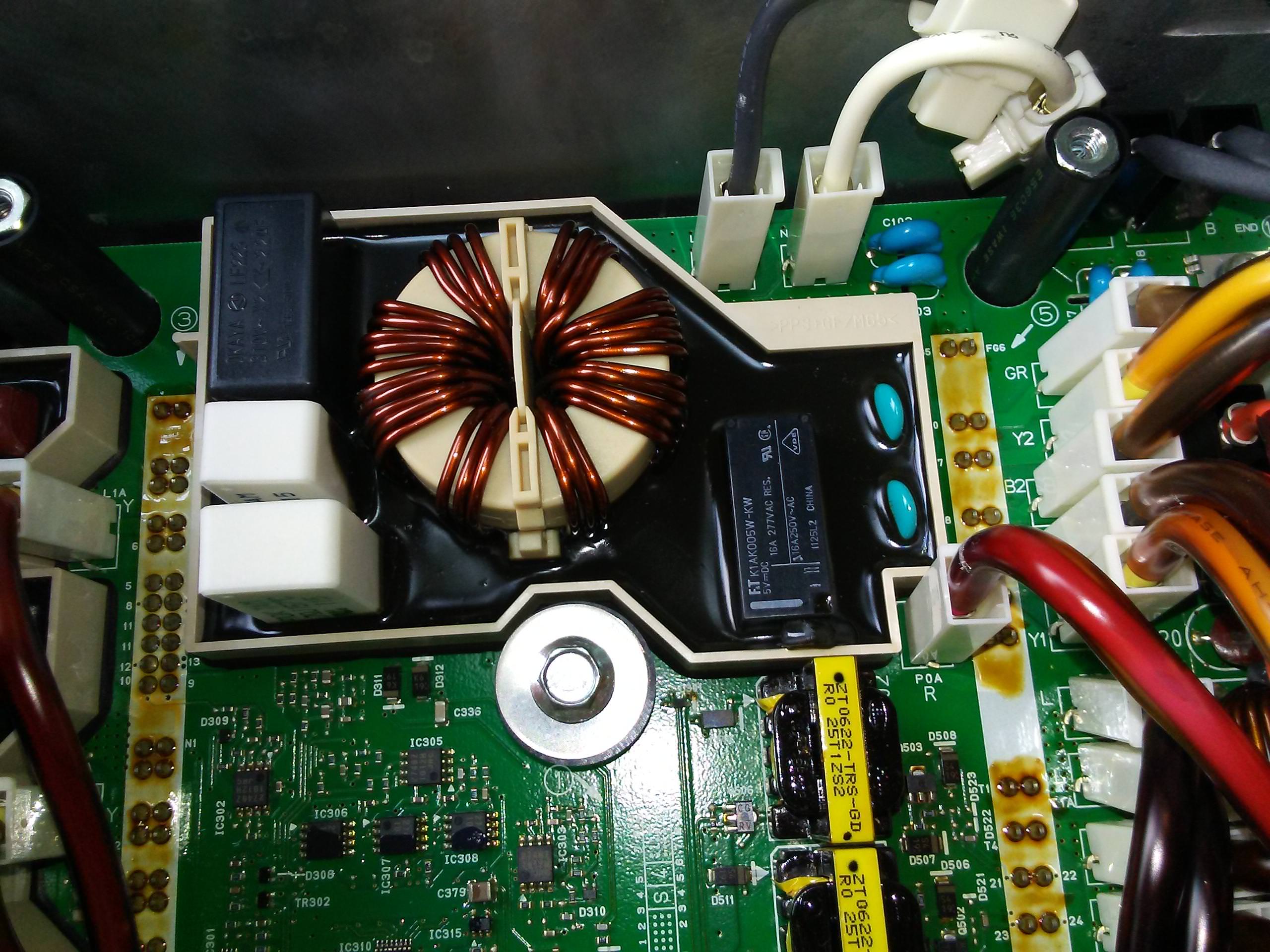
So we removed the top board, and low and behold there is some soot on a component of the bottom board. Further investigation found that it is an upright board where the soot originated from, which contains two surface mount resistors. One of these had popped its top, and spewed its remains on the black resin casing below it. Houston we have found our problem.

So, what to do now. We have a few options, first of all I may be able to replace the expired resistor, but I need to work out what the resistance of that resistor was. This is also a difficult job due to the placement of the resistor, so I have to be careful to not damage other components in the process. Option 2 is to work out which board contains the VIN locking (extortion coding), is it the top board, or the bottom board. The top board does appear to contain a chip, which may be the MCU for the board, however tomorrow I plan to remove the bottom board and see if I can locate any chips that may be a MCU on that one. If the extortion coded MCU is on the top board only, then we may get away with replacing the bottom board from a wrecked iMiEV.

So at this point we are still considering our options, I think I may attempt a repair first. After-all, I cannot make it any worse, just need to work out what resistance the resistor had (it has loads of resistance at the moment ).

The moral of the story, go with your gut, not the dealer, as they will replace component after component, rather than actually investigate the actual cause, and they will raid your bank account in the process.

Photos attached.
34750839_10213791958525457_878849586930647040_n.jpg
 
@electron

sorry to hear of your troubles and such poor service and treatment by the stealer.

i bought a mut-clone scanner tool, the Carsoft i909, which will read the DTCs. It won't let you re-do VINs for ECU changeout, but is very handy to get the trouble codes and data.

Is that black potting compound like a flexible rubber, or a solid epoxy?
 
electronpusher, so sorry to see you jerked around by the Mitsubishi dealer. Their mis-diagnosis cost you time and money and their refusal to do right by you reflects horribly on not only the dealership but Mitsubishi Australia Ltd., as well as the Mitsubishi Corporation - a sure way of stopping future product sales to you, the customer!

Regarding your burned-out resistor - a resistor is rarely the cause of a problem but, especially in power circuits, it often acts as a fuse when, for example, a downstream capacitor shorts out. IIRC, kiev discussed this elsewhere on this forum.

electronpusher, thank you for your discussion and photo, wish you well in further diagnosing and fixing the problem, and do let us know how things progress. Good luck!

PS. Whereabouts in Australia are you? How To Let Us Know Where You're Located
 
Ok, an update.

I think board with the blown resistor has been bonded to the water cooling layer of the DC/DC Converter, it does not appear to want to budge, and I do not want to break it. Possibly it could be attached from underneath, but it does not appear so.

We drained the coolant, and then removed the DC/DC Converter from the car. On the bottom side of the DC/DC Converter is another cover, which we removed. On this side is another board, which has some high voltage components on it. We have not attempted to remove this board as we need to be able to drive the car in a few weeks to our new home shortly.

So for the time being, we will be putting everything back together tomorrow, so that we can drive it to our new home. It has enough energy left in the battery to make that drive, and it still drives just fine.

Once there, it will need to sit for a few months as we have stuff we need to do to the house, so this is where this saga is going to end for the moment.

We have not yet decided on how we are going to proceed, as we are considering our options. We may end up getting a second hand DC/DC Converter, and swapping out the top board from our car into the second hand part. I have a feeling that the IC on the top board is where the VIN Locking of the part is occurring, as it was the part that was connected to the cars CAN BUS. We may get away with simply swapping that board over to the second hand part, which will be wonderful news for all the other people out there with the same problem. We may end up writing it off financially, and sell for parts.

The other option may be importing an iMiEV from Japan for parts, and simply swapping out the Battery MCU, Motor Controller, DC/DC Converter and cars ECU, which are all the VIN locked components.

But we don't know just what we are going to do at this point.

So if anyone knows someone wrecking an iMiEV who would be happy to part with the DC/DC Converter, or if anyone has any advice on how we could import the part from Japan from a wrecked iMiEV over there, please let us know.
 
Looks like a different layout used in the US 2012 versions--i opened mine up to read that resistor value for you and my unit doesn't have that vertical board such as yours.

There was scorch marks under my cover where the inductors and transformer wires got warm and off gassed the plastic tubing.

OD2diIc.jpg


Here is the AC input and CAN buss connection of the top board with physical barrier isolation. The potted doghouse is the surge arrest and suppresion for the AC input.

gvpMsYV.jpg


Flipped over the top board to see the processor, IC701 marked as R5F71424FPV, likely a Renesas microcontroller. Nothing else would likely store the VIN on the bottom board, so swapping the bottom board and keeping the top board would probably work for you.

2tuo9J3.jpg


Here on the bottom board is the EMI filter and AC input relay doghouse with flexible rubber potting which can be easily removed with a spudger stick or bamboo chop stick whittled to a flat blade on one end and a pencil sharpener on the other.

The bottom board is held in with 10 fasteners that are numbered and have direction arrows for the removal or installation sequence.

[edit] It does not require de-soldering to remove the board.

The filter surge capacitor is marked OKAYA LE225, 310Vac X2, which would be across the mains before the coil. The bigger white ceramic resistor is marked P102K TAM 4.7 Ohm J, rated for 157 degrees C. Couldn't read the smaller one.

H8HMxD3.jpg


Another view rotated to read relay markings, 5Vdc coil with 250VAC 16Amp contacts. Maybe there is a board buried under where the two blue caps are sticking up?

jzsbpvZ.jpg


Your board may be a snubber circuit for the relay coil, or a circuit to bootstrap power for the relay from the AC mains. The TCCH/Elcon chargers use a bootstrap circuit and have a failure mode where the bypass resistors will blow such as yours did. The value in those chargers is 75R created by two 150R 5W resistors in parallel. There are some great fellows down under, e.g. Coulomb on the AUEV association forum, who would probably help you fix it.

Does your car have DC quick charge, level 3 charge port? i posted how to close the relays to get direct access to the pack + and - thru the Chademo port. Even if you don't, there are other ways to push electrons back into the pack that bypass the onboard charger.
 
kiev said:
Maybe there is a board buried under where the two blue caps are sticking up?
Actually, those "caps" are a slightly different blue to the others. I suspect that these are NTCs (negative temperature coefficient resistors), which are often used for soft starting / pre-charge. Their resistance starts high, they quickly get hot, and their resistance then drops dramatically.

Things may be a little different between the American and Australian models due to the difference in mains voltage (120 V versus 240 V, though we sometimes pretend that ours is 230 V). The Japanese models would presumably expect 100-120 V mains, while European models expect 220-240 V. Since the US and Japanese markets are presumably much larger than the others, they might use the daughter board to house something special for the less common Euro/Australian markets. The daughter board might have held more NTCs in series, or they might use NTCs of different characteristics. There could well be other changes to accommodate the roughly 2:1 difference in expected mains voltage.

I'm guessing that this part of the circuit is mains related, with a 250 V relay nearby. I don't know this charger/converter as yet, so I could be way off base.
 
Wow, talk about a supportive community! Thanks Kiev, coulomb, electronpusher and Joe!
Do ya think that the extra insulating sleeve of clear vinyl that 'browned out' is still a good thing, or would removing it allow for better wire cooling and prevent future full failure/ short circuit? Just popping the zip ties could be a start to prevent heat buildup!

Here's a link to Kiev's post about activating the CHAdeMO contactors for HV Pack access at the DCFC port.
http://myimiev.com/forum/viewtopic.php?f=24&t=2001&p=35097&hilit=close+relays+CHAdeMO#p35097
 
I'm guessing that this part of the circuit is mains related, with a 250 V relay nearby.

I am thinking the same thing. The iMiEV does not have a proper EVSE so to speak, it is pretty much a cable that goes from the 240V socket to the DC/DC Converter. Now the iMiEV charge cable lacking the EVSE would dump any surge from the 240V socket into the DC/DC Converter, rather than kill the EVSE. This may explain the large number of iMiEV's that are having their DC/DC Converters killed.

If/when we fix ours, I think we will dump the iMiEV charge cable, and use the EVSE that we have for our Outlander.

So the next question is, will a Japanese DC/DC Converter work for our car (with the top board swapped over), or do we need to source one from a 240V friendly country such as EU or UK? I did note that ours had the abbreviation GBR on top of the DC/DC Converter, this may mean it was a converter for the UK market. It does however also have V110 written on it, now is this refer to voltage, or version number?
 
Thanks Kiev for all the useful information. It is interesting the different components on your DC/DC Converter compared to ours.

We are at this point considering sourcing a DC/DC Converter from somewhere, be that Japan (if compatible) or the UK. However as I suspected, it appears the Japanese delivered iMiEV can take either 110V or 230/240V, just like US delivered EV's, as while they may have 110V for their normal domestic supply, 240V is also available for appliances that require a higher voltage, such as a clothes dryer. The following from Mitsubishi confirms this:

For normal charging i-MiEV is connected to either a standard 100-volt or 200-volt domestic outlet using the charging cables supplied with the vehicle.

https://www.mitsubishi-motors.com/publish/pressrelease_en/products/2009/news/detail1940.html

So based on that, I think we should ok to source the DC/DC Converter from Japan. Hopefully the VIN Locking is occurring on the top board, and hopefully it is not damaged.

Thanks for all the wonderful knowledge from you all.
 
Kiev: Does your car have DC quick charge, level 3 charge port?

Yes, it does have DC quick charge, and we are considering borrowing a CTEC CHAdeMO charger from someone here in Sydney, and seeing if we can put charge in that way. We will however still need to charge the 12V battery separately since it currently does not charge from the battery or 240V. This will give us plenty of electrons to get the car out to our new home.

We will probably import a DC/DC Converter from a wrecked car in Japan, and swap out the top board to see if that fixes it. If not, then we will probably sell parts or the whole car as is.
 
kiev said:
Howdy Mike, welcome to the miev forum.
Hi. I may be starting an interest in iMievs, for a colleague.

I was thinking those blue caps were like the 2 Y caps of an EMI filter such as this: ... and it read: HR R 102k
Yes, that clinches it. Now I'm thinking that electronpusher's "resistors" may have been surface mount versions of those Y capacitors. They all look much the same when burned. Is this possible, @electronpusher ?

With the chargers seemingly so voltage agile, I can't see any reason for resistors in one model and capacitors in another. Maybe they changed the circuit, perhaps for reliability problems. So I agree that swapping the bottom board should be ok. Weird that the mains conditioning is on the DC-DC board though. I guess it's just where it fitted.

Edit: some more thoughts. It looks to me now that both the charger and the DC-DC are on the bottom board. That's why the mains goes there. The mains comes in on two orange wires (with active marked as black, the US convention, and strange to we Aussies where black usually means neutral), and the charger output (to the battery) goes out on the other two orange wires at the bottom of kiev's photos. There is a green there too (hopefully with a yellow stripe) that goes to ground/earth/chassis.

So the top board seems to be all control logic, plus half the mains conditioning: fuse, surge arrestor, X capacitor and bleed resistor (which doesn't seem to be visible under the potting, but you can see its symbol under the PCB), and three movistors (MOVs, Metal Oxide Varistors, which are voltage dependent resistors, basically more surge protection). The surge arrestor appears to be in series with two of the MOVs, one each to active and neutral. So actually, electronpusher, there is a fair bit of protection on the mains side. I'm moderately impressed. The potting seems to be to keep dust and grime (even though this box is probably sealed) from making paths for the higher voltage, and to keep high voltage parts and tracks away from fingers. It also has the effect of mildly frustrating repairers, but safety and longevity are obviously more important. Electronpusher, does your surge arrestor (designated "SA" on the top board) look as-new as does Kiev's?

Another thought: perhaps "soot from resistor" is actually arc flash from inside. I've seen this with Elcon chargers. Is that possible?
 
It's a dual function box--it does both the dc/dc for the 12V, and the ac/dc for the pack charging.

Here's what i think we are looking at: the 3 big electrolytic caps and coil at the rear of the box (bottom edge of picture) are the rectified dc buss , the diode bridge and FETs for PFC are mounted to the water-cooled heatsink underneath the board, as are the PWM boost FETs, and the output cap and coils are toward the front (top edge of photo).

In the scorch picture, the fat shiny orange cable harness runs from this box to the pack terminals inside the motor inverter located to the right. So there is HV when the pack contactors are closed, either for charging or in READY drive mode.

i've posted some notes of my findings about these cars on my fat stacks and morning wood blogsite: http://fsamw.myevblog.com/i-miev-technical-stuff/
 
coulomb: I was thinking those blue caps were like the 2 Y caps of an EMI filter such as this: ... and it read: HR R 102k
Yes, that clinches it. Now I'm thinking that electronpusher's "resistors" may have been surface mount versions of those Y capacitors. They all look much the same when burned. Is this possible, @electronpusher ?[/quote]

Quite possibly, won't be able to check that for a while though as it is all back together now so we can drive it out to our new home. Out there we intend to remove it again, and we'll clean up the soot from that area, and see if I can make out any markings on the remaining component.

I also agree that there would be no reason for them to be resistors, if other models have caps, so my assumption now is that they are resistors. It may be repairable yet.

The concern I have with protection on the mains side is that it is all contained in this one $4000AUD box, which if a surge does occur, they want to replace the whole thing. With an EVSE the cost is cheaper for replacement.

As with the soot, I guess it could be HV discharge, but the only thing it would have discharge to was the relay next to is, as there is not burn marks anywhere else. Kinda hard to say.
 
electronpusher said:
It may be repairable yet.
True. But unfortunately after a massive transient like that, blowing some parts to soot, it's likely that there is damage to other parts of the circuit.

As with the soot, I guess it could be HV discharge, but the only thing it would have discharge to was the relay next to is, as there is not burn marks anywhere else.
I don't think it was flash-over; it seems more like a massive overload.

I mean to say that the discolouration on the relay might be from internal arcing of the contacts, rather than external deposition from the blown components. When you get to it again, it would be good to distinguish between those two.

If the relay opened under load, which could happen if it lost power, then there is significant current in the Power Factor Correction inductor. This is also seen if you disconnect power to an Elcon charger when they are charging at full output. Inductors don't like to have their current changed instantly, like from 14 A RMS (so around 20 A peak) to zero. If you try, then they develop high voltage (of the order of kilovolts) to try and keep the current flowing. This is likely to take out the X and Y capacitors we've been talking about, but unfortunately also the bridge rectifier, the PFC MOSFETs (they could be IGBTs), and some snubber components.

Oh, duh. I've just realised that the input relay likely has the same function as on the Elcon EV chargers: to short out the pre-charge resistor. One of the large white vertical power resistors could be the pre-charge resistor. Though it is on the wrong side of the common mode choke. I'm thinking now that on some models, the pre-charge resistor is a through-hole component under the potting mix, and on others like electronpusher's, it's an array of larger surface mount resistors on a small daughter board. So the soot may have come from resistors after all. It's quite common (perhaps 30-50% of cases) for the pre-charge resistors on an Elcon charger to be burned up or high or low (!) resistance. Any time that the input relay opens under load, if it has the pre-charge resistors across its contacts, the pre-charge resistors will attempt to take full load current, possibly full mains voltage if there is a short circuit or near short further down. They often fail in spectacular fashion. Perhaps electronpusher's Y capacitors are smaller, kiev's capacitors have longer pigtails, so the tops of these capacitors isn't visible above the potting.

Then there is the reason that the input relay opened under load. If you don't recall switching off the charger at the mains (as opposed to getting the car to switch off charging digitally), then it could be another fault elsewhere that knocked out the power to the input relay. On Elcon chargers, the common failure mode is an electrolytic capacitor going high internal resistance from age, and it's protecting the main MOSFETs from switching transients. One MOSFET pair shoots through, shorting the DC bus, which causes an overload and also knocks out the power supplies, so the input relay opens. On a 2 kW Elcon, the parts to fix all this comes to well under AU$100. It might me a little more for a 3.3 kW iMiev charger, but still way less than AU$4000. Unfortunately, it takes hours of labour to do all this, and this is with a schematic diagram of the charger, and a web page with repair tips.

But maybe the iMiev chargers are better protected, and it's mostly the pre-charge resistors that blew. We just won't know until further investigation.

I'm a total iMiev noob, so I have no idea what the availability of schematic diagrams for things like the charger/DC-DC module. Are they available?
 
Howdy Mike, no schematics yet, but Paul is on this forum also [piev] and we might have to trace it out and draw it up for another round of schematics and troubleshooting/repair. So far it hasn't been necessary, but e-pusher's issue may require it.

i think one of those big white ceramic resistors is part of the EMI filter, and the other is for by-pass or pre-charge such as the 150 Ohm parallel pair in the TCCH/Elcon.

In addition to the internal surge suppression on the top board, and the EMI filter in the relay doghouse on the bottom board--externally bolted to the top of the charger is another input EMI filter with an X2 safety cap. It is actually the first filter since the AC mains from the EVSE comes thru this board before entering the charger. Hopefully that will raise your moderate impression a bit toward the next level.

JNeaF6R.jpg


This is a picture of the dc/dc board in the bottom-most plenum of the charger box, located underneath the coolant plate. The fat pink and blue wires are the HV to/from the top plenum, seen on the top edge of the bottom board photo (upthread). The big fat white wire exiting after the 125 Amp fuse is the B+ routed to the positive terminal of the 12V Aux (starter) battery. There is also a smaller S (Sense) wire to the aux positive.

GwAW0Dv.jpg


Here is a top-level block diagram from Mits showing the charger flow, but it doesn't show the external EMI, surge suppression or relay.

rpCUDqc.png


And one for the dcdc converter.

MBn14Z1.png


These little cars are a blast to drive, you should grab one up if you can. i drive 50 to 60 miles everyday on a single charge and they are perfect for commuting.

cheers,
kenny
 
Kiev,

the charger block diagram is almost the same as for the Elcon EV chargers, except:
* The PFC transistor is a pair of PFC MOSFETs in the Elcons
* The Elcons' switching devices are MOSFETs, not IGBTs

I didn't realise that the DC-DC was in a separate compartment. I assumed that one transformer was for the charger, the other for the DC-DC, But I see that the DC-DC transformer's output is copper ribbon, needed for the high current.

So what is the second transformer for in the charger box? There is only one in the block diagram. Perhaps there are two identical charger units in parallel, each with its own transformer, IGBTs, etc.

I'm glad to see that the DC-DC main switches have 0.2" spacing leads. The Elcons' MOSFETs are 0.1" spacing, and it's too easy to get a leakage from drain to gate, in my opinion.

Yes, my being moderately impressed by the iMiev charger/DC-DC has increased a few notches :)
[ Edit 2018/Aug: However, I note that only a few models seem to have the EMI box on top of the regular charger box. ]
 
electronpusher, thanks so much for this video, which will give someone further confidence to tackle the repair themselves. Interesting to see the mirror-image of things under the bonnet compared to the LHD version. BTW, on the US version, disconnecting the airbag connectors underneath the seat sets the airbag warning flag which I dunno if the i909 can reset.
 
Part 2, finally edited and uploaded. hope this helps.. also, there could be other failure modes, that this might not fix.

https://youtu.be/ynFKclou-LI

Thank you to Kiev, Coulomb an Mikedufty for all your help, without you guys we wouldn't have taken on this repair. your expertise and willingness to help others is very much appreciated.
 
Back
Top