You are using an out of date browser. It may not display this or other websites correctly.
You should upgrade or use an alternative browser.
You should upgrade or use an alternative browser.
The Troubleshooting and Repair for On-board Charger (OBC) Thread
- Thread starter kiev
- Start date


Help Support Mitsubishi i-MiEV Forum:
This site may earn a commission from merchant affiliate
links, including eBay, Amazon, and others.
On my board the larger sized one in the series string is a "274" .
The other 2 smaller ones are both "331".
The other 2 smaller ones are both "331".
PM message from Vitaly,
Moving the discussion here so that others can benefit.
Sounds like the AC may be getting turned ON, but there is some issue on the Power Board that is triggering a shutdown. First, Verify continuity of the L and N lines from the AC input thru to the solder junctions of the waffle plate on the power board. Check/test/verify the operation of the little black AC input relay.
Hello
Are you from Kyiv?
I'm Vitaly. From the topics on the forum, I noticed that you are very good at repairing electric cars.
I need help with repairs On-board charger Nissan Leaf ZE0 2012y
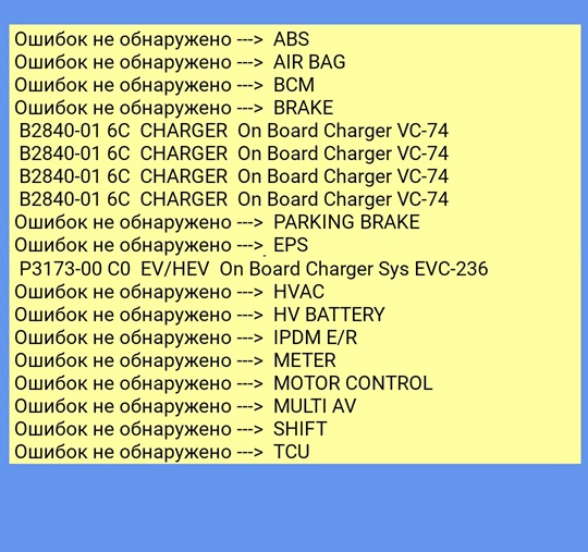
Knocks out the error code B2840-01 6С and P3173-00 С0
The wafer was damaged, I replaced the H-bridge IGBT, 1μF input capacitors and 3.3μF, 4.7Ω 5W resistors, but the converter does not work, there are no Н-bridge control pulses.
the car tries to charge and after 5 seconds it turns off and throws errors
Thanks
Moving the discussion here so that others can benefit.
Sounds like the AC may be getting turned ON, but there is some issue on the Power Board that is triggering a shutdown. First, Verify continuity of the L and N lines from the AC input thru to the solder junctions of the waffle plate on the power board. Check/test/verify the operation of the little black AC input relay.
Hello
Yes, indeed the charger for Leaf ZE0 and Miev were made at the same factory and have an identical scheme with minor differences
So, I have a non-working charging module from Leaf ZE0, it is visually intact, has no visible defects, but does not want to work. First of all, the lines L and N were checked for serviceability, with them everything is OK on the waffle plate AC is supplied, the relay is also working, I checked for the absence of overestimated contact resistance
The large PFC capacitor is charged to 380-385V and then the module is silent, the H-bridge does not even try to start.
Yesterday, I had the opportunity to connect the processor board from another of the same charging module, and the board began to behave differently: in the first few seconds, the voltage on the PFC capacitor reaches 380-384V, and after a few seconds, the H-bridge charging circuit starts to output 378V (on battery at that time before charging was 375V), then the voltage on the PFC capacitor drops to 350V, and after a few seconds the module stops working with errors B2840-01 6C and
P3173-00 C0
https://imgur.com/a/g9gv9kl
The P3173 DTC is set by the VCM when the OBC detects a fault and notifies the VCM. In this case the fault is likely related to whatever caused the B2840. There are 4 cases within the B2840, designated A,B,C,D in the Factory Service Manual, but seem to be numerical -01,02,03,04 on the OBD scan tool.
The FSM gives some voltage and current and timing conditions which can throw this code, but it is all quite useless without going into detail of which circuit to check or how to fix the problem.
B2840 DTC DETECTION LOGIC
CAUTION: Never use extension cables to charge the battery.
NOTE: DTC “B2840” may be detected by the use of extension cables for normal charging of Li-ion battery.
DTC detecting condition
A
ON BOARD CHARGER (General electrical mal- function)
• Duringnormalcharging,thePFCoutputvoltagein the on-board charger is 412 V or more for 0.1 second
or more, or 345 V or less, for 11 seconds or more.*1
• Duringnormalcharging,thePFCoutputvoltagein
the on-board charger is 450 V or more for 1 second
or more, or 345 V or less, for 11 seconds or more.*2
• Duringnormalcharging(100V),theon-boardcharg-
er DC output current is 10A or more for 5 seconds or
more.
• Duringnormalcharging(200V),theon-boardcharg-
er DC output current is 18 A or more for 5 seconds or
more.
• Duringnormalcharging(100V),theon-boardcharg-
er DC output current is abnormally lower than the on- board charger command current value for 5 seconds or more.
• Duringnormalcharging,theDCvoltageoutputbythe on-board charger is 440 V or more, or 240 V or less for 5 seconds or more.
• Duringnormalcharging,thePFCcircuitintheon- board charger operated however an abnormal status is continued for 1 second or more.
B
ON BOARD CHARGER (Component internal mal- function)
• Whennormalchargingisstarted,aDCvoltageoutput by the on-board charger of 460 V or more is detected.
• Duringnormalcharging,theDCvoltageoutputbythe
on-board charger is 200 V or less for 10 seconds or
more.
• Duringnormalcharging,theACvoltageinputintothe
on-board charger is 293 V or more for 5 seconds or
more.
• Duringnormalcharging,amalfunctionisdetectedin
an on-board charger internal circuit.
• Duringnormalcharging,theACcurrentinputintothe
on-board charger is 22 A or more for 5 seconds or more.
C
ON BOARD CHARGER (Component or system over temperature)
During normal charging, abnormal high temperature of an on-board charger internal circuit is continued for 100 seconds or more.
D
ON BOARD CHARGER (Parametric)
Ripple amplitude in output voltage of the on-board charger remains extremely large for 5 seconds or more during normal charge.
DTC
Possible cause
B2840
On-board charger
• ACpowersupply O • EVSE
• On-boardcharger


$26.99
KISHACZ 4 PCS Car Door Lock Cover for Mitsubishi i-MiEV 2009-2020, Car Door Latch Lock Protective Cover, Door Latch Lock Cover, Door Latch Guard Car Decorative Accessories,B Black
Yuanpingshilixiuhanshangmaoyouxiangongsi


$29.99
Car Tissue Holder for Mitsubishi i-MiEV 2009-2020, Car Napkin Cover for Car PU Leather Car Visor/Backseat Organizer Hanging Paper Towel Clip Car Accessories,Orange-1
hongchuangbaihuoshangdiangerenduzi


$150.00
$299.99
EP Home Smart Electric Vehicle Charger, 40 Amp Level 2 EV Charger, NEMA14-50 Wall Indoor/Outdoor Electric Car Charging Station, 240V, 25 Ft Cable
Energy Pro Cable


$85.99
$107.99
Powerbuilt 5-Piece Box End Insulated VDE Wrench Set, Rated for 1000V, Sizes 7mm-14mm, Electric and Hybrid Vehicles, Home Electrical and Car Repair - 642962
Northern Tool + Equipment


$15.99
Built Industrial Adjustable 3 Jaw Oil Filter Wrench with Adapter and Plier Tool Set for Auto Care
Infinite-Commerce


$28.99
FIPOISA Car Rear Bumper Protector for Mitsubishi I-Miev, Carbon Fiber Trunk Door Sill Protection Strip Sticker, Trunk Door Entry Guards Plate Decorative Accessories
yuanpingshizhanghongyushangmaoyouxiangongsi


Vitaly, did you check the diode drops at the solder terminals of the waffle plate? That might help identify if there is a problem there.
I tried to check the waffle plate as much as possible, I did not notice any problems with it.
Thanks for the detailed description of the error codes, they gave me some ideas, if I'm wrong somewhere, I'll correct them right away.
So, for maximum protection and correct operation, the OBC monitors the voltage at 3 points:
1. AC input voltage,
2. Voltage on the PFC capacitor,
3. Voltage at the output of the charger
The OBC also monitors the output current supplied to the battery.
If at least one of these parameters is not normal, then charging will definitely stop.
I assume that the OBC should in any case keep the output voltage no higher than 400V, even when there is no battery.
After these assumptions, I decided to conduct one rather tough experiment for the OBC, I disconnected the battery of the OBC, connected a voltmeter to the battery terminals and turned on the charge, the result did not please me at all, I got 500V! that is completely unacceptable.
And currently I suspect that OBC does not see the output voltage
coulomb
Well-known member
The back end of a battery chargers is a current controlled device, expecting to see a huge battery there to absorb the bursts of energy emitted. With no battery there, its voltage control will be expected to be very poor. So it may be that this is OK, though I'll admit it's a bad look.LDTVN said:After these assumptions, I decided to conduct one rather tough experiment for the OBC, I disconnected the battery of the OBC, connected a voltmeter to the battery terminals and turned on the charge, the result did not please me at all, I got 500V! that is completely unacceptable.
And currently I suspect that OBC does not see the output voltage.
Elcon/TC chargers have a relay between the back full bridge and the battery, but it's bypassed with a diode and high value (≈100 kΩ) resistor in series across the contacts. So with no battery, you are seeing the back end of the charger. An Elcon however won't even start the back end if it doesn't see battery voltage. Maybe there was residual charge on some capacitors, and it thought it saw some battery voltage, enabling it to start up.
You might be able to see some CAN bus messages with measurements; if so that should indicate if if any are way off.
Edit: It was months ago that I did this, so I'm hazy, but my CAN bus related posts seem to start about here.
There are several low voltage power supplies on the upper logic control board; these voltages can be measured at the electrolytic caps.
If the waffle plates seems to measure good, and the AC Input circuit is working (AC getting to the power board), and the PFC cap is getting charged up...then i'm thinking there might be an issue on the control board, especially if you swapped it out and got some different reaction.
The current feedback circuit can be found by searching for the "twisted sister resistor" post and the discussions around there. All of those feedback signals go thru optical isolators on the power board and thru the white wires and connector to the control board.
Thanks to everyone, the problem is solved!
Kenny, thank you for the key clue in solving the problem.
coulomb, quite an interesting post about CAN, I will deal with it.
In general, I am interested in how it is possible to test and run electric vehicle modules on a table, especially charging modules.
So, regarding the solution to the problem described above:
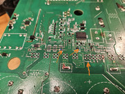
My guesses were confirmed, there are 3 resistors of 330k each at the output of the module under the compound, these resistors failed, the charger lost control of the output voltage and started throwing an error
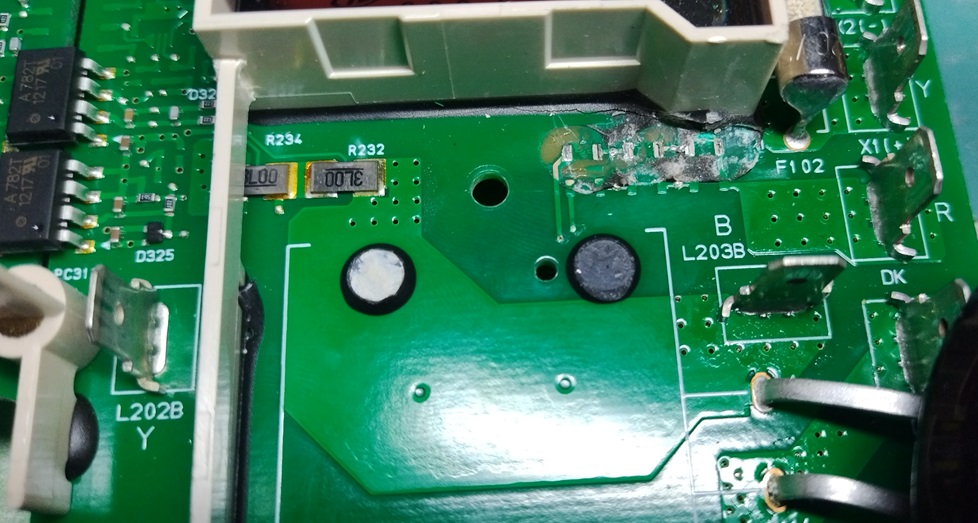
https://imgur.com/a/ddOWrxO
Now we need to repair one more module, but more on that later, now we need to replace the H-bridge transistors on the waffle plate
Kenny, thank you for the key clue in solving the problem.
coulomb, quite an interesting post about CAN, I will deal with it.
In general, I am interested in how it is possible to test and run electric vehicle modules on a table, especially charging modules.
So, regarding the solution to the problem described above:
My guesses were confirmed, there are 3 resistors of 330k each at the output of the module under the compound, these resistors failed, the charger lost control of the output voltage and started throwing an error
https://imgur.com/a/ddOWrxO
Now we need to repair one more module, but more on that later, now we need to replace the H-bridge transistors on the waffle plate
My experience with the multitude of ribbon cables connecting all the boards on a Canon Digital Camera:
Mark a line across the ribbon where it enters the socket with a Sharpie.
Then you will know how far to re-insert the ribbon, and whether it is square-on.
Mark a line across the ribbon where it enters the socket with a Sharpie.
Then you will know how far to re-insert the ribbon, and whether it is square-on.
Bonjour j'ai un code defaut avec la valise sur ma voiture imiev code POAOA impossible de charger avec la prise secteur
Après elle roule très bien pas de défaut au tableau de bord, si vous av6une idée
Merci
Hello I have a fault code with the suitcase on my car imiev code POAOA impossible to charge with the mains socket
Afterwards it drives very well, no faults on the dashboard, if you have an idea
THANKS
Après elle roule très bien pas de défaut au tableau de bord, si vous av6une idée
Merci
Hello I have a fault code with the suitcase on my car imiev code POAOA impossible to charge with the mains socket
Afterwards it drives very well, no faults on the dashboard, if you have an idea
THANKS
Daniel11 said:Bonjour j'ai un code defaut avec la valise sur ma voiture imiev code POAOA impossible de charger avec la prise secteur
Après elle roule très bien pas de défaut au tableau de bord, si vous av6une idée
Merci
Hello I have a fault code with the suitcase on my car imiev code POAOA impossible to charge with the mains socket
Afterwards it drives very well, no faults on the dashboard, if you have an idea
THANKS
Howdy Daniel,
That code indicates that someone has been messing around with the High Voltage service plug located under the left hand seat. That plug gets pulled out as a safety interrupt when servicing the HV pack. Here is some info from the factory service manual about that code.
Reference: http://mmc-manuals.ru/manuals/i-miev/online/Service_Manual/2012/54/html/M154920530001900ENG.HTM
OPERATION
The service plug switch in the main battery sets the service plug state to the EV-ECU by means of the service plug switch signal.
DIAGNOSIS CODE SET CONDITIONS
When the signal of the service plug switch in the main battery is turned off, the diagnosis code No. P0A0A will be set.
PROBABLE CAUSES
Damaged wiring harness or connector(s)
Disengagement of the service plug
Malfunction of the main battery
Malfunction of the EV-ECU
makey
Member
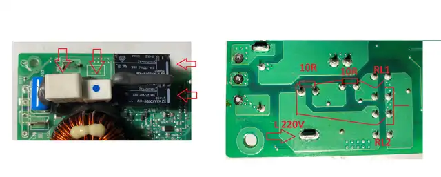
Hello everyone, have you already had to repair the second generation OBC? The manufacturer solved the burnout of the resistors by installing another relay (see photo), which, after charging the capacitors, disconnects the resistors (10+10 Ohms) from the circuit.

https://imgur.com/a/mlfNE3y
It is possible to add a similar relay to the old version of the OBC, but the question is how to connect it correctly?
https://imgur.com/a/mlfNE3y
It is possible to add a similar relay to the old version of the OBC, but the question is how to connect it correctly?
coulomb
Well-known member
Extracted image:
It seems we'd need a fairly simple circuit that powered up the pre-charge-via-resistor at power on, and turns it off one second or so later. If the other relay hasn't come on by then, it likely never will, so save the pre-charge resistors.
It should be possible to design a small PCB that fits all this with a minimum of flying wires required. Perhaps use a small modular power supply that uses the L connection that is needed anyway. Or something clever that uses a safety rated capacitor, since the coil power will be low, and is only needed for a short time.
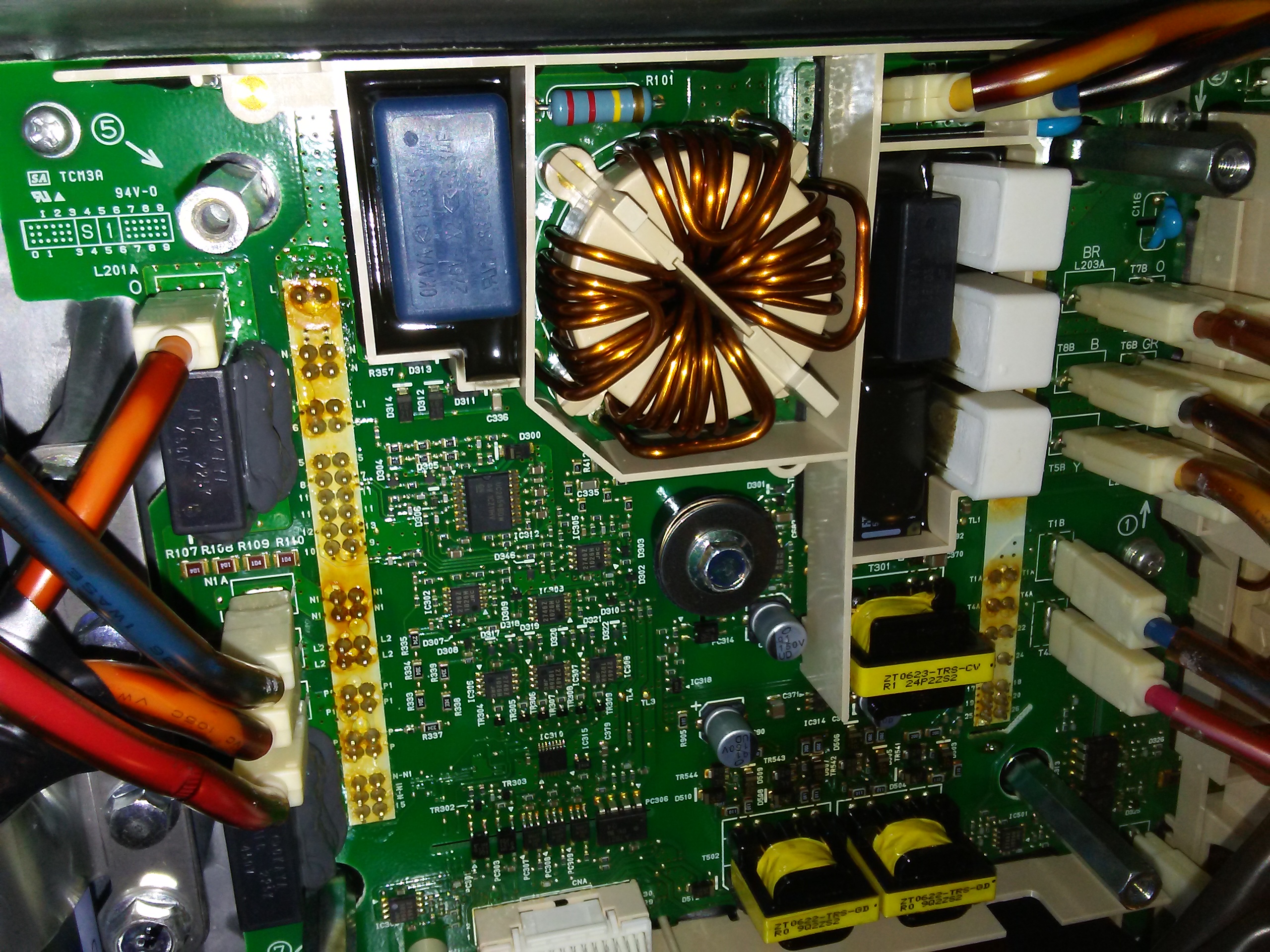
A gift for forum members: a detailed schematic of a waffle plate CZ1525RPWR012
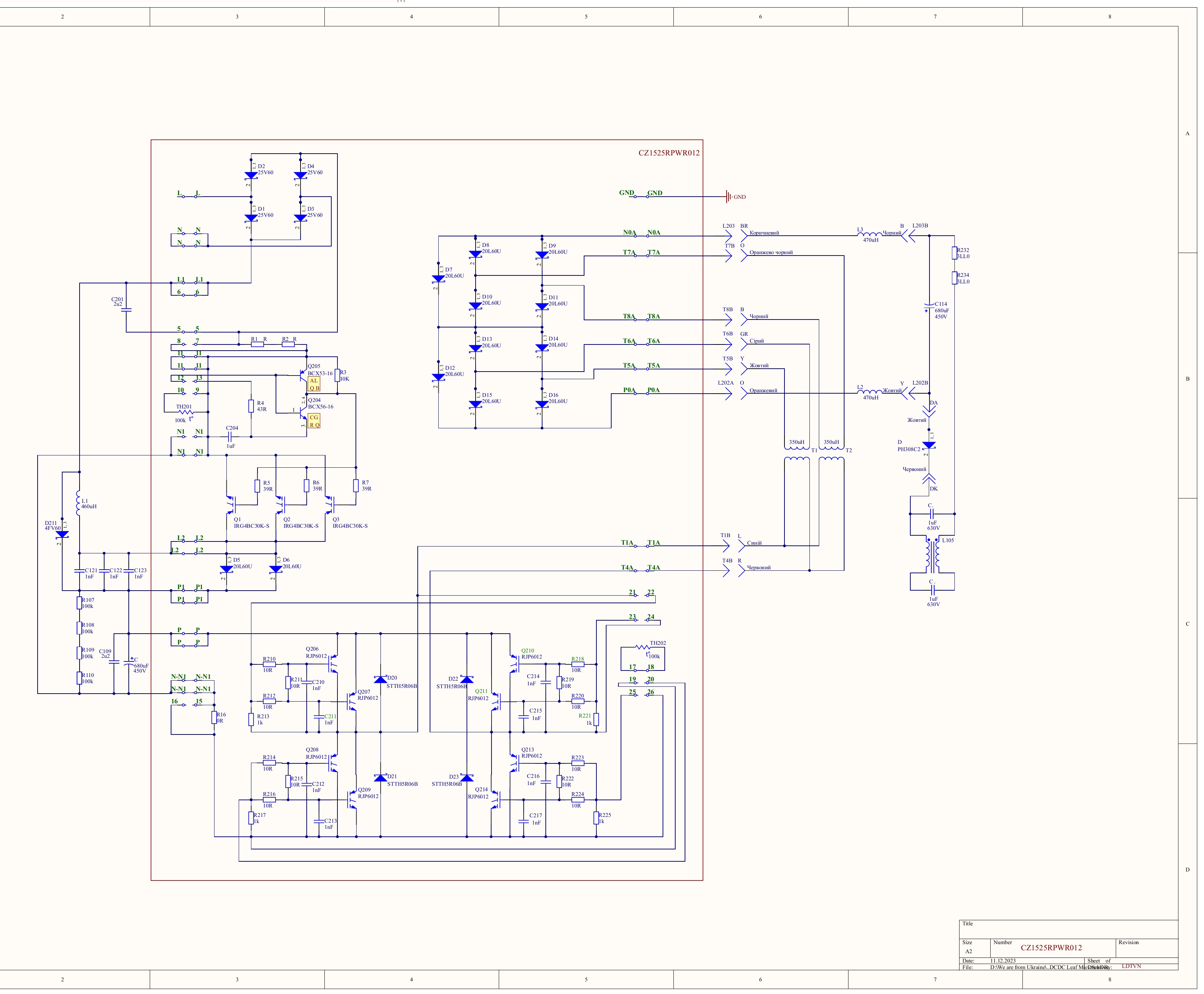
https://imgur.com/hZCmAZk
https://imgur.com/hZCmAZk
Thank you very much for the schematic!
Hi, what a great place to get information on repair of on-board charger and other related issues. Read about 10 pages and learned a lot but my problem was solved easier than re-soldering new capacitors or fixing a waffle plate. Thought to leave it here anyway in case someone experiences the same issues as I had since I haven't found any similar (or exactly the same) issue described. So here is my story.
Bought a car and was using quick chargers for a 400 km trip, an experience on its own! When got back home put it on 230V charger that came with the car. The charging started fine but stopped in about 1,5h. At reconnecting the charging was starting and then stopped in a minute. I asked the previous owner and he hasn't had that issue before (of course) but he says he only used slow type 2 public charging stations, not the 230 V charger. It turned out that after the car sat for a day it would again charger for about 1,5h and the story starts again. The strange thing was that 3 h was not enough, it had to rest for longer. Since the temperature outside was around 0 C, it was strange since if some component got overheated, 3 h would be more than enough to cool it down. I couldn't check any public charging station at that time because the car was not registered and could not be insured. Looking on the internet found this page but also people reporting having problems with the same/similar charger. The input cable is often tightened too much when it comes into the "box" which leads to one of the leads breaking after some time. Mine was fine on the input side but very suspicious on the output side. After disassembly and striping the wires no braking wires were found, put everything together but the problem persisted.
I had an original 12 V PSA battery and I read at several places that when it goes old the voltage is too low for activating the relay and starting charging. I measured the battery voltage and it had 14.3 V at the terminals when the charging was ongoing and a bit lower when the charging stopped, probably around 13 V. So that didn't seem to be a problem. Also, even though the car is from 2011 I think the battery was changed already at one of the yearly services. There is a sticker saying that it "expires" at the end of 2022. It is hard to believe the producer would trust the battery will be good for 11 years.
When the car was registered I drove it first to a yearly control and then tried to charge at the nearby type 2 station. It didn't want to start charging at all. Left it at home for a day and planned to go to another station the next day. Then I tried again at the same station the next day. The station is just 300 m from where I live. Sure enough, it started charging, but, sure enough, it also stopped in 45 min.
I read about that sometimes relays (two of them I think) cause charging problems. So what I did is to remove all the relays, cleaned the contacts (some minor corrosion on some of them but nothing too bad) and swapped them around so that no single relay ended up at the same place. To remove the relays the 12 V battery needs to be disconnected first to avoid any shorts. The realys are hard/impossible to pull by hand. I ended up bending some thin wire to make something that looks like a keycap puller (google it) and then pulling it up with plies. The 12 V battery terminals looked corroded, one terminal worse than the other but nothing that I would think of as a heavy corrosion. Also, it is a strange selection of batter/leads they used, hard to justify why they select a battery with so thin terminals but cables with a bigger diameter of clamps so that a lead "spacer ring" needs to be used. That is an extra connection point to corrode. Anyway, after everything was cleaned the main battery charged like a charm without any stops. If it wouldn't I would test to connect my other car's battery with jump wires and charge the main battery like that to make sure it is not the 12V that is causing the issues.
Even though I cannot be 100% sure I think the problem was with an aging 12V battery and corroded terminals. When I measured the voltage I did it at the terminals but probably the voltage at the car was lower. I think when the car sat for a while the battery went a bit lower on charge, when the charger was connected the voltage was enough to close the relay and activate the charging. Probably charging of the 12 V battery was activated immediately also so the OBC got stable 14 V during the period the 12 V battery was charged up slowly. When the charging of the 12 V stopped probably the voltage at the OBC dropped and it shut off the charging of the main battery. When it was reconnected again there was almost no need for charging the 12 V battery so it shut off much faster. That would also explain why I couldn't start charging directly after driving - the 12 V battery was charged during driving.
I will of course change the battery now but wanted to leave it here and contribute to someone experiencing the same issue
Hello
I have a problem with my 2012 miev with 80.000 km on the clock.
THe OBC starts to charge but after 5 sek it stops. I have been reading about this problem and decided to check the ceramic resistors in the OBC doghouse. Both of them are burnt but no signs of other damage. I live in Iceland and parts are not availible here so I am in littlebit dilema what I should do.
Can I send the OBC somewhere to have it rebuilt?
Thanks in advance
Attachments

Similar threads
- Replies
- 5
- Views
- 617
- Replies
- 21
- Views
- 2K
- Replies
- 0
- Views
- 724
- Replies
- 6
- Views
- 8K
- Replies
- 5
- Views
- 2K