[ The P1A15 Troubleshooting Thread ] No READY. P1A15 error. Condenser charge timeout.

Mitsubishi i-MiEV Forum

Help Support Mitsubishi i-MiEV Forum:

This site may earn a commission from merchant affiliate links, including eBay, Amazon, and others.

Lic

Well-known member
Joined
Dec 28, 2015
Messages
104
Location
Canada
INDEX to this thread. [Mod Edit, moved Lic's original fault history to post #5]

[Edit, june 22, 2023 after going thru entire thread]
This is a P1A15 INDEX Post with links to help find pictures and info quickly.

Repair approaches to solve this problem:
1. Add resistor(s) to the hybrid to change the Gain of the op amp stage.
1.1 Add resistor in parallel along the voltage divider before the hybrid to raise the input voltage to the hybrid (e.g. Sandrosan's repair on page 37
2. Replace a defective component on the hybrid board.
3. Replace the entire hybrid board with something else.

A nice set of pictures from Stan uploaded by coulomb: Stan's pics
Photos of the hybrid board:
Picture of the hybrid board with added resistor to change Gain of Amplifier
Bottom view of hybrid board with latest markups on page 36

Nihon block diagram of hybrid: Nihon FBD
Analog Devices AD202 block diagram: AD202 FBD
Scope trace of the precharge event: scope trace
Added 11/2023 from page 50, Martin's scope capture
HV measurement thru the hybrid isolation board:
MCU HV Overview page 23

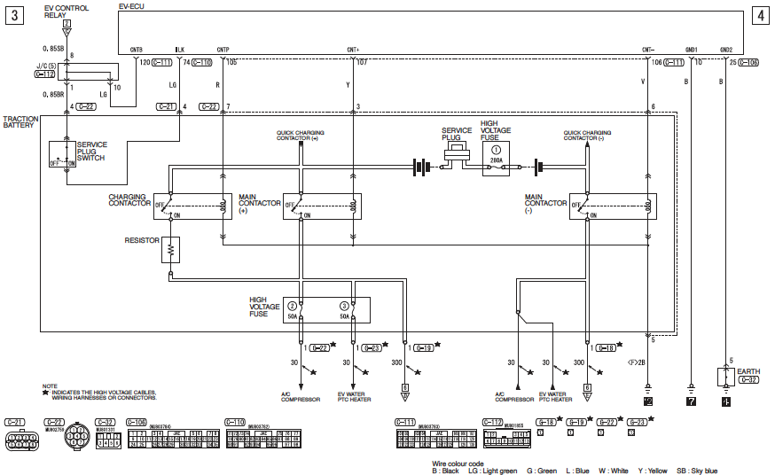
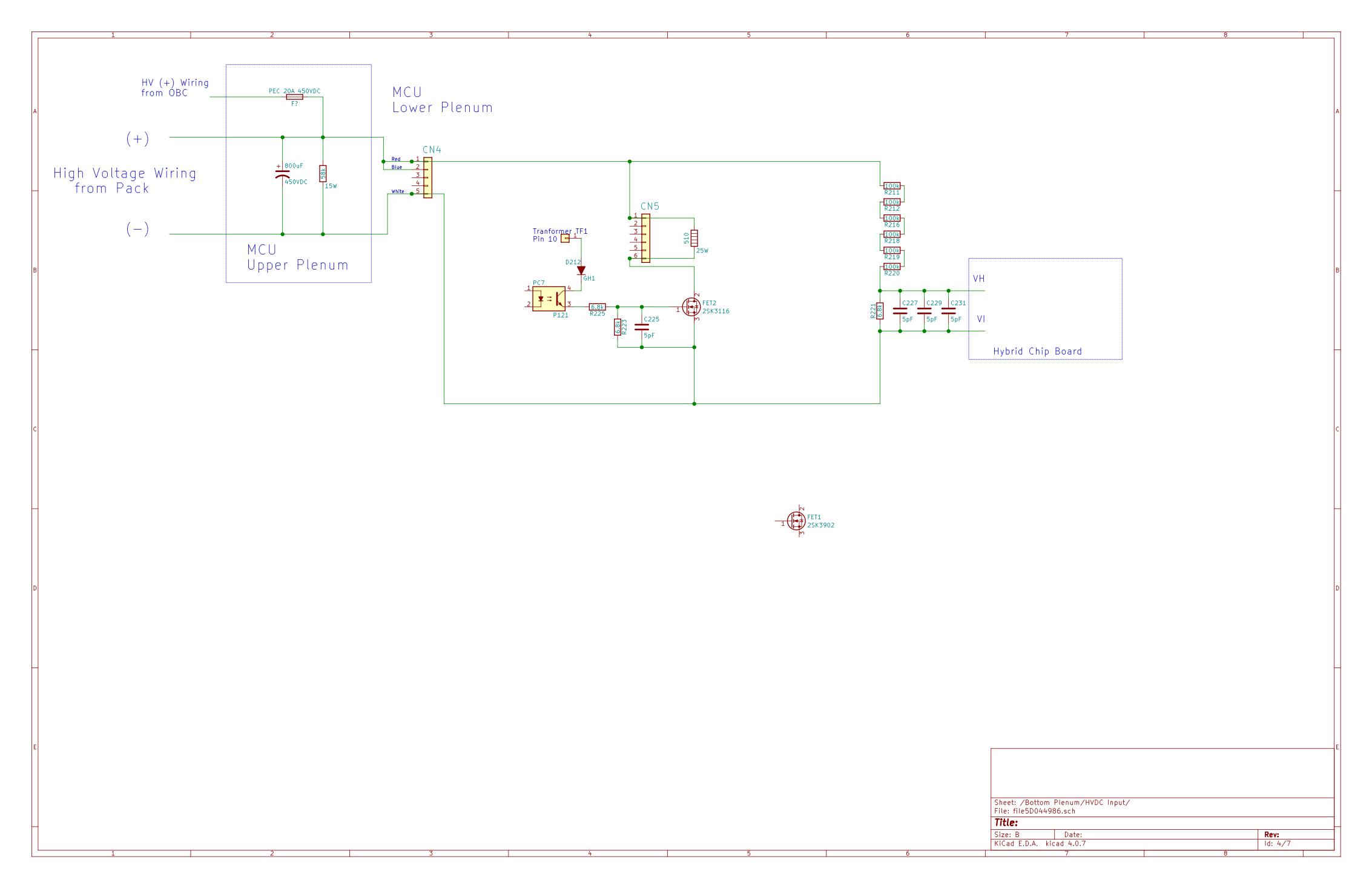
HV circuit to the Hybrid: sketch of circuit
Hybrid circuit details:
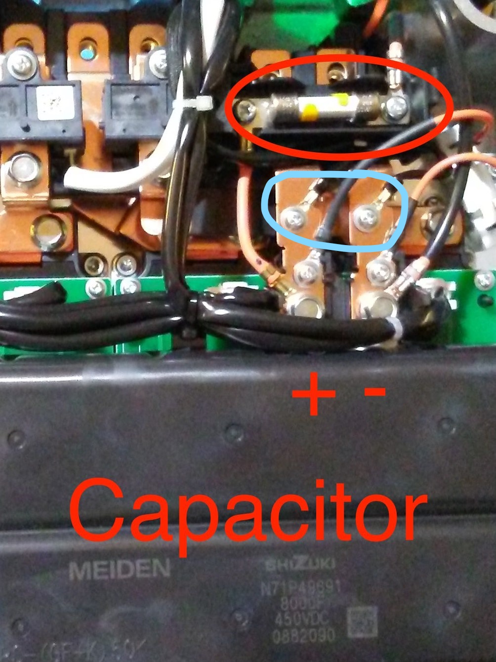
Some component values on page 14: C and R values
Identification of components page 19: IC part numbers

Beginning of long detailed troubleshooting with Justin on page 16 [runs thru page 37]:
boo the good german shepard
detailed troubleshooting hybrid scope trace page 34

Replacing the hybrid with something else:
Greg Fordyce proposed replacement with alternate part AD202 starts on page 38
Justin's custom wiring solution for Greg's board on page 43
Vanthi's custom board is also on page 43 at the bottom

Repair Videos:
drcat's repair video is on page 46
drcat video
Daniel's repair video is on page 47
DalatheGreat video

David's OBDZero Pid Listing is on page 44:
OBDZero PID list
this INDEX is a work in progress and open for suggestions.
[/end edit]

===== Original Reply starts here =====

Probably not a good idea--member redcane had the same issue and tried to enable the contactors and blew the precharge resistor:

http://myimiev.com/forum/viewtopic.php?f=22&t=4194

You still don't know whether or not the EVECU has tried to command the main(+), but it may be so quick that a scope would be needed to see it. Precharge only takes about 0.125 sec (see scope trace in redcane's thread) and 97% is close enough to full such that the car should turn on the main; there is only 0.4 Amps flowing at that time.

i can think of at least 3 scenarios:
bad contacts, the EVECU is commanding main(+) and the car is trying to go to READY by turning on the MCU and DCDC, and they are the load that is pulling the buss voltage down.

Or bad indicator, the EVECU is commanding main(+) but the indicator is not showing movement and the EVECU is shutting down.

Or other component, the EVECU is not commanding main(+) due to some other issue.
 
Last edited by a moderator:
coulomb said:
Lic said:
I used diagnostic software and made video of what is going on after turning key to ready position. I left link for video here earlier.
Ok, that would do it! Sorry, I somehow missed the video links earlier.

It seemed to get to 338 V, which is only 12 V short of the battery voltage of 350 V, and is 97% of the way there. You won't get a lot better than that, it seems to me. But then it plummets to 70 V before the timeout and the main positive contactor never comes on. I note that the contactor status flags sometimes lag, e.g. there was over 200 V on the capacitor while the negative contactor was still listed as "off" (which is of course impossible). So perhaps the exact timing and sequence of events can't be totally trusted. But the fact that it did get to 338 V at one point, and was at 70 V on the next sample, suggests that something is draining the capacitor before the capacitor is declared charged.

I wonder how they prevent the DC-DC from using any charge (apart from charging its own capacitors), and whether that delay (from initial power-on to actively drawing power) could be too short. You might be able to test this theory by temporarily removing the combined DC-DC and OBC 20 A fuse; at least it would isolate the problem to either the DC-DC or OBC, or something else (e.g. motor controller, flashover, air conditioner, heater, one of the battery contactors).

BTW, what diagnostic software is that? (Pardon my ignorance there).
I am using chinese launch x431.
Today I opened small MCU window and checked what voltage is on pack wires when I try to switch on car. I used 2 voltmeters (good chinese and fluke). Both showed similar numbers something around 344-346v. (one time flukee showed 351v and chinese showed other time 349v). I used them separately. Unfortunately I was not able to find good analog voltmeter which should be better to check increasing voltage on main battery wires.
Next I checked 12v battery. It showed 12.6v (connected to car), 12,4v when key turned half way and 12.25v when key turned full way and relays in pack started to clicks.
Next I checked voltage on ev-ecu connector on contacts for main(-) contactor and precharge contactor. Main (-) showed 12.05v and it was easy to monitor it because main (-) starts first and disconnects last. Precharge showed 11.98v and it is look like it works only 1 second.

Tomorrow I want to manually engage main(-) contactor and precharge contactor and see what stable voltage from battery I can see on main battery wires. if is not good idea please tell me.
 
Last edited by a moderator:
Lic said:
Tomorrow I want to manually engage main(-) contactor and precharge contactor and see what stable voltage from battery I can see on main battery wires. if is not good idea please tell me.
That sounds like a good thing, but be prepared to disconnect quickly, as it seems to me that something is putting a load on the battery before pre-charge is fully complete. But it would be good to know this for sure, being able to take a few seconds for a digital multimeter to settle.

However, if there is a significant load on the battery, then the pre-charge resistor will be seriously overloaded. About 10 seconds of running the motor, wondering why it seems so slow this time, can lead to this. It took a week for the smell to go away. And of course, the pre-charge resistor is buried inside the battery pack, where it's not easy to get to. But a few seconds with really only the DC-DC, air conditioner, or heater as possible loads, hopefully won't hurt.

One thing I'd consider is forcing your multimeter out of auto-ranging, on the 400/600/1000 V range, so that it doesn't have to waste time overflowing the 4 and 40 V ranges before settling. [ Edit: the less time the pre-charge resistor is (potentially) overloaded, the better. ]

Oh, and John Fluke would be spinning in his grave ;) [ Edit: from the mis-spelling of his name. ]
 
Index moved to post #1.

== Original Reply starts here

@Lic said:
Tomorrow I want to manually engage main(-) contactor and precharge contactor and see what stable voltage from battery I can see on main battery wires. if is not good idea please tell me.

Probably not a good idea--member redcane had the same issue and tried to enable the contactors and blew the precharge resistor:

http://myimiev.com/forum/viewtopic.php?f=22&t=4194

You still don't know whether or not the EVECU has tried to command the main(+), but it may be so quick that a scope would be needed to see it. Precharge only takes about 0.125 sec (see scope trace in redcane's thread) and 97% is close enough to full such that the car should turn on the main; there is only 0.4 Amps flowing at that time.

i can think of at least 3 scenarios:
bad contacts, the EVECU is commanding main(+) and the car is trying to go to READY by turning on the MCU and DCDC, and they are the load that is pulling the buss voltage down.

Or bad indicator, the EVECU is commanding main(+) but the indicator is not showing movement and the EVECU is shutting down.

Or other component, the EVECU is not commanding main(+) due to some other issue.
 
Last edited:
[Edit this is Lic's history of this DTC that kicked off investigation and separate thread for P1A15]
Apr 2018
Lic said:
I didn't use car long time and I got died 12v battery.

Lic said:
So i connected tester and got errors p1a15 active and p1ae6 saved.
Lic said:
Canion sees battery fine, no problem with cells. It even showes me that car should show ready, but it does not.
Lic said:
after sometime while i played with launch tester x431 it appeared again. This tester kind of poweful. I am able to test some car system. But i didn't find test to try to close main contactor. I looked cells - look like they are fine. Max disbalance is 0.01v, battery voltage is 350v.
June 18
Lic said:
i didn't have time to look car, so i decided to go to dealer to check car and may be to fix it....

Lic said:
but when i switched car off at home and switch it on - i got same problem and same errors. so i don't understand what is going on. most likely i will go to dealer and i will ask them what exactly they did to car.

Lic said:
so i looked car by launch tester and only serious error was P1A15.... i erased it and car showed ready. when car is show ready condenser voltage is 340v and real battery voltage is 350v.

Lic said:
i did small video about how reacts voltages and contactors positions when i am trying to switch on car and it doesn't start. i will show it if somebody interesting.

Here is video of fail switching on car.


Jan 19
Lic said:
So after long time I returned to repair car. All those time car was sitting on driveway.

PS I didn't use car from Jun 17. Before car had capacity around 36ah. Right now as I can see it has capacity in BMU settings only 29ah. I left car with around 67% SOC. For me it is strange that car lost so much capacity when it was just sitting on driveway.

coulomb said:
Lic said:
I think I will try to open MCU and look condenser, but I am not sure what exactly to check. Any suggestions?
I would think it's not likely to be the capacitor ("condenser" is an ancient term for capacitor); it would have to have *extra* capacitance to cause this problem. [ Edit: Sigh. I contradict myself below; it could also be that the capacitor has very high leakage, but that seems unlikely. ] I think it's more likely to be one of
  • Pre-charge resistor
  • Pre-charge or one of the main contactors (positive or negative)
  • Something causing extra load on the high voltage side, e.g. blown components in the MCU, or more likely given the history we've seen, the On Board Charrger. In particular, it might be those small capacitors in the OBC that blow so frequently. If the DC-DC and OBC 20 A fuse hasn't blown but those capacitors are shorted, then you won't be able to achieve ready.
  • The auxiliary battery, especially since it's had ample time to discharge with all the little loads that cars have, and we know that a weak auxiliary battery can cause all sorts of problems. In particular, it might not be able to pull in three contactors, if it's really weak.
It could be the capacitor in the motor controller having very high leakage, but it would need to be nearly a dead short for that leakage to prevent readiness. That's the only part mentioned above that's in the MCU (apart from the 20 A fuse, and it's accessible via a cover), and inside you will see this:

Screen%20Shot%202015-10-02%20at%209.10.48%20AM_zps9nqwry8b.png


The capacitor is the large black thing with "MEIDEN" written on it. Unless it's melted or otherwise visibly deformed, I doubt that you'll be able to determine much by looking at it, unfortunately.

Only the auxiliary battery is easy to test/fix. Give it a charge with a 12 V charrger, since the DC-DC can't charge if from the traction battery without achieving ready (battery connected to HV circuits, such as DC-DC input). If it's older than say 3 years, replace it. If none of that helps, you'll need to try and measure the drain on the high voltage bus, without electroplating yourself. How confident are you with this sort of thing? I've heard of people activating contactors manually and measuring the resistance of the pre-charge resistor, but this is far from trivial if you're not set up for that sort of thing, and of course one end of the resistor you'd be measuring is connected to traction battery positive.

Lic said:
12v is fine for sure. I have actually 3 around me. One of them 6 months old original mitsubishi i-miev battery. It is fully charged and checked for capacity and ability to provide good current without big voltage drop.
I am fine to work with hi voltage battery. I have a lot of experience with repair and modifying my 116V electric scooter.

I don't think there is a problem with extra load on hi voltage side. When dealer kind "repaired" car - I drove and charged car without any problems. Car showed regular 0.4A consumption from big battery on parking shift in ready mode. It was nothing unusual except it doesn't show ready after restart.

So I think the same - I need some how check precharge resistor and main contactors. Is there information how manually switch on main contactors?

coulomb said:
Lic said:
Is there information how manually switch on main contactors?
Find the original of the below on http://mmc-manuals.ru/manuals/i-miev/online/Service_Manual/2013/index_M1.htm .

Thb7SMg.png


From the Troubleshooting and repair for On-board Charger (OBC), DC-DC Converter topic, first page.

You will then have the pinouts for the connectors, just energise what you need with a 12 V supply or battery, with the service plugs disconnected. I have no idea how practical this is to do with a car on the ground. See also Imiev repair - precharge resistor (Australian Electric Vehicle Association forum). I don't think that the contactor coils are polarity sensitive (e.g. economiser present, or catch diode), but perhaps it's worth checking.

today I checked by scope signals from ev-ecu to main(+), main(-) and precharge contactors. I was able to see main(-) and precharge signals, but not main(+). Then I tried to manually engage main(+) contactor and I hear clamping noise from battery. Then I tried to manually engage main(-) and precharge contactors and see what voltage I can get on main battery wires. I saw stable 348v. I don't know what to check else. May be it is time to go to dealer again.
 
Last edited by a moderator:
The workshop manual says that the capacitor voltage is measured in the MCU and sent to the EVECU over the CAN buss. At one time you were having some CAN error DTCs--have those returned or is it all cleared? i would guess CAN is okay since you can read the condenser voltage using the phone app.

Link to online FSM, P1A15 troubleshooting page

In summary, after checking for good CAN buss, then the connectors, then the wires, then for intermittent faults, the FSM indicates to replace the MCU or the battery pack depending upon whether pack voltage is greater than 220 VDC. i would guess that the wiring is okay since you can read the voltage when you did the manual control of the precharge and (-) contactors, and the capacitors are okay since the voltage held steady, and the pack cells are okay by the voltage.

One possibility not listed is the transistor device within the EVECU that switches 12V power to the main(+) coil, but it does seem that the EVECU may have internal diagnostics to set a DTC for such a failure mode, P0ADB.

P0ADB troubleshooting

The only other test i can think of might be to remove all HV loads except the MCU; disconnect or remove the 20A fuse from the MCU to eliminate the OBC and DCDC, and disconnect the HV lines to the heater and Air Conditioner compressor. This would eliminate external loads that could be pulling down the HV during the time after precharge and before main(+).

The Aux battery seems to be getting pulled low just for powering some relays at START. Maybe you could put a scope on it to catch the transient during START to see how far it is being pulled down. Many folks have had issues resolved by replacing a weak, old or worn out Aux battery. Here is a link for testing the Aux battery. They measure battery voltage after 15 seconds with a 130 Amp load.
 
I decided to go to dealer again. They asked $118 per hour only for diagnostic and they expect 3-6 hours for diagnostic or may be even more :(
 
Dealer did procedure for P1A15 and told that problem should be in inverter which cost $8k new. :(
 
MCU RECALL NOTICE
There was a recall on some cars for the inverter (aka the EMCU, or MCU). i wonder if your issue is somehow related to the reason for the recall? It might be worth asking them for consideration.

found online
http://www.dft.gov.uk/vosa/apps/recalls/searches/expand.asp?uniqueID=5453A311769CBC9180257E960033FAA5&freeText=Blank&tx=0.3765833

Vehicle Details
Reference : R/2015/156
Manufacturer Ref : R3028610
Make: MITSUBISHI
Model : I-mIEV
Launch Date : 21/09/2015
Numbers Involved : 33
Build Start Date : 09/08/2011
Build End Date : 29/08/2011
Recall Details
Concern : VEHICLE MAY CUT OUT
Description : Due to none conformity during manufacture the resistance of the insulated base inside the motor control unit (MCU) which controls the electric motor, may decrease. As a result, the voltage in the circuit may become unstable causing the warning light to illuminate and the driving motor power to be restricted to the fail safe control. In the worst case scenario the vehicle may not be able to be restarted and the battery may not be able to be charged.
Remedial Action : Recall the vehicles that are likely to be affected and replace the engine MCU.
Vehicle Id : JMALDHA3WCU000220 to JMALDHA3WCU000259
 
Yes, I can ask. I don't think if it help, but I will try. Thank you for you help!
 
Lic how are u progressing with repair? I have same Condenser code on and 8k repair telled..

What was this feature which allows code reset for 2-4 times with Citroen maintenance Official tool? But after that even it cant reset it? I have motor controller condensator code now resetted 3 times and now its locked. How it it resetted again? Those 3 resets maded in same afternoon so no any change on car between resets..

What can even Official maintenance do in this situation? Can they someway reset this 3 time reset countet? Maybe it need somekind of total reset to hole system. Or firmware reload?

1. Reset was ok without any change and car started ok. But after turned off for minute it didnt restart.it got same conderser code but it code didnt clear. It needed disconnect dcdc for code to be removed.

2.start were ok again. But when tryed reboot it got code again. Even dcdc still disconnect code didnt be clear able.. then i disconnect ac compressor but still code jammed. Last disconnect heater and then code was remove able and car started for last time.

After 3. Turnoff same restart try again but no start and code was on again and not remove able.cant disconnect any more devices so its totally dead now.

Do you guess its Capasitor or precharge problem? Disconnecting last devices seemed help 2 times.. it was on November so it was about 5c degree car. So that also drop condensator abilities..
 
I installed used MCU. Unfortunately it has VIN inside from car from which it was taken and so far I didn't find way how exchange this VIN to mine. So I have error P1B2D VIN mismatch right now. I want to go to dealer and ask if they can fix this problem. I tried to put MCU's VIN to EVECU and P1B2D disappeared but P0513 - incorrect immobilizer key- come out. I was not able to rewrite my key to system. It asks immobilizer PIN and I don't know this PIN to do it.
I heard that originally this problem came from wrong voltage understanding by car and could be kind of easily fixed by installing right resistor in voltage divider in MCU. I didn't try this way yet.
 
Why did you try to write to the EVECU, you just needed to load the VIN into the MCU?

http://mmc-manuals.ru/manuals/i-miev/online/Service_Manual/2012/00/html/M100101520068500ENG.HTM
 
I'm in the same situation. Citroen C-Zero year 2011 bought second hand on 39k kilometers. Error P1A15 - No READY and cannot be charged. The battery pack is fine. CanIon shows all cells to be at 4 v with .05 variation at 70% charge.

The dealer said it could be the A/C Compressor or the Heater. After they cleared the code for the first time the car started as usual and managed to drive for 10-15 km to bring it back home. On the next "ignition" the error came back.

The first thing was to replace the auxiliary battery, but it didn't help.

I scanned the car and cleared the code with Diagbox software. On the next start I monitored the capacitor voltage and it goes to 340 v. The battery pack is 350+.
I disconnected the A/C Compressor and cleared the error code but still it comes back when I try to start the car. Tried to clear it again but it appeared almost immediately. Finally I managed to clear it again from another menu of the Software and with the charger plugged in.

I couldn't disconnect the heater because i didn't find its plug. The C-Zero and I-Miev maybe use the same platform but have quite differences.

Next I'll try to open the MCU and the OBC to check if there is something wrong starting with the 20v Fuse and checking if all connections on the bus are all right.

This forum is really helpful after reading for a couple of days I understand the car more and love it even more despite that I managed to drive it for 10 km before it broke right after I got it (Lucky me)
 
Here is picture inverter main board. I read eeprom chip from board and i can see vin number inside. So it should be CRC inside eeprom, right? Does anyone has access to same chip? I need several dumps from different cars to find out CRC and how it calculates.
attachment.php
 
i have that board out of an inverter but haven't traced the circuits.

The 100-pin quad flat-pack chip with reference designator U1 with the white label is marked 64F7047F40V, a Renasas 32-bit RISC microprocessor.

U2 is a 48-pin qfp, AU6803, resolver to digital converter chip.

i could try to read this board--What is the reference designator of the eeprom, what is the chip and the protocol to read it?
 
U6 is eeprom.
https://www.st.com/resource/en/datasheet/m24c64-r.pdf
Any bios chip reader should be able to read it.
I used CH341A programer to read it, but there are a lot of different devices which could read this chip.
 
Where does these two wires are connected to the main board?
DJnqXH2.jpg


Maybe in the lower right corner of Lic's picture? They should be for measuring the voltage of the capacitor. Could it be that there is some kind of a failure in the measuring circute and it cannot measure correct capacitor voltage? This is the only logical explanation left.

I disconnected them and tried to start the car. The capacitor charged to 349 v and held the charge. The battery by Lexia is shown at 352 v. Discharged the capacitor trough the bleeding resistor.

I haven't disassembled the MCU yet. Just wanted to make sure what to look for before jumping in the deep water. This will be the next step.

I found a thread that there was a problem with the discharge circuite, but they didn't mention how they fixed it.
 
Yes it does go to the bottom of the lower right corner of Lic's photo, to Connector CN4, labelled "VDC". The red and blue wires are from the (+) side of the pack and route to pins 1 and 2; the white wire is from the (-) side of the pack and routes to pin 5.

CN4p1 then routes to CN5p1, labelled "VDC-R", which is a red wire running to the large silver-colored resistor on the heatsink, ~50W power resistor, 510 Ohms. The other end runs back to CN5p5, thru a white wire. This is the quick bleed resistor for the large "condenser", the big black 800 uF capacitor in the top plenum. CN5p5 routes to the Drain of the big FET2; the gate is driven by the output of optocoupler PC7; and the Source is connected to pack (-) thru CN4p5. This RC combination has a time constant of about 0.4 seconds and would drain the big cap in about 1.2 seconds.

In parallel from CN4p1 is a voltage sensing circuit running from CN4p1 to a series string of six 100k resistors and a 6.8k that route to the hybrid chip board pin 1 labelled "VH" with the return on pin 2 labelled "VI", that connects back to pack (-) thru CN4p5. This is a voltage divider to drop the high voltage down by a factor of ~90: for 360 Volts at the condenser, the voltage at the Hybrid is about 4 Volts.

If any portion of that sense hybrid circuitry were not working properly, then it may be that the HV is not reading properly.

Your test to remove the jumper wires at the pack buss bars seems to indicate a problem down below on the main board in the bottom plenum of the MCU. Did the car go to READY when you ran that test? i would guess not, but you did prove that the bottom circuit is pulling down the pack voltage at the "condensor" and throwing the P1A15 DTC.

[edit: corrected some hasty notes from yesterday and added details of voltage divider and fast bleed resistor; and sketch of circuit]

sketch of circuit
MX7IUyz.png
 
Back
Top