Battery current sensor

Mitsubishi i-MiEV Forum

Help Support Mitsubishi i-MiEV Forum:

This site may earn a commission from merchant affiliate links, including eBay, Amazon, and others.

coulomb

Well-known member
Joined
Jun 10, 2018
Messages
527
Location
Brisbane, Australia
I'm considering modifying the main battery current sensor output to allow use of higher capacity cells in the imiEV battery case.

The current sensor seems to come out on 10-pin connector C26. Anyone know where this connector (male and female) can be purchased?

Does anyone know the consequences of modifying (reducing) the value of current read? For example, will this affect the maximum motor power?

Also, does anyone know what the high and low control values are about? I assume that there are actually two sensors, both output 2.50 V at zero current. My guess is that one has 10x the resolution of the other, and so the other has 10x the range of the first. I assume that the two have to agree within certain tolerances or there would be a trouble code produced.
 
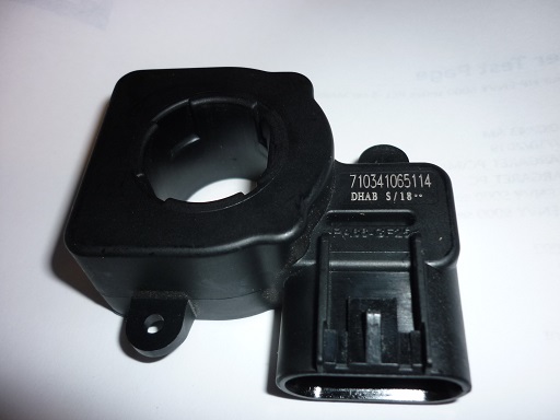
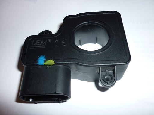
The current sensor itself:

HVKEb7V.jpg
rTWx1uo.jpg


The blue and green paint was just something the owner used to keep track of the connectors and where they go.

Edit: the large number 710... seems to be the world's most high resolution date code (with the leading 7 for the Beijing factory). Possibly down to the tenth of a second, unless I misread the datasheet. Or maybe there is a check digit.
 
Thanks for posting the picture--that's a first time to see the sensor. i'll have to look for an LEM datasheet.

So you are looking for the connector and mate for the oval-shaped [rounded rectangular] housing to make a break-out box for the wiring?

DHAB
High performance Dual range (high/low range outputs) current sensor +/- 1000A,suitable for high performance Battery management system.

Their website doesn't list the S/18** part, but i see you beat me to it...

Why do they not identify the mating connector on the datasheet? how useless is that
 
kiev said:
i'll have to look for an LEM datasheet.

Here is one: https://www.electronicsdatasheets.com/download/1589.pdf?format=pdf

So you are looking for the connector and mate for the oval-shaped housing to make a break-out box for the wiring?
I would have said more rounded rectangle, but now that I look again, there does seem to be a very slight curve on the long edges. It's one possibility I'm thinking of. Especially before I knew about the two outputs, thinking two resistors might do it :twisted:
 
> Oval-shaped housing

Oh, I see what you mean, the connector as pictured. That's buried inside the battery box; most inconvenient. I meant connector C-26 on pins 2,3,7,8. C-26 is just outside the battery box. It's a standard looking connector, though still likely hard to find.
 
i would guess it's a JAE connector since so many others are from them. Is pin1 populated?
Here's my notes on C-26:
1
2 CS +5V
3 CS CSIG
4 BMU AutoNumber OuT
5 BMU CANH

6 Shield Ground
7 CS LSIG
8 CS C Ground
9 BMU AutoNum IN
10 BMU CANL
 
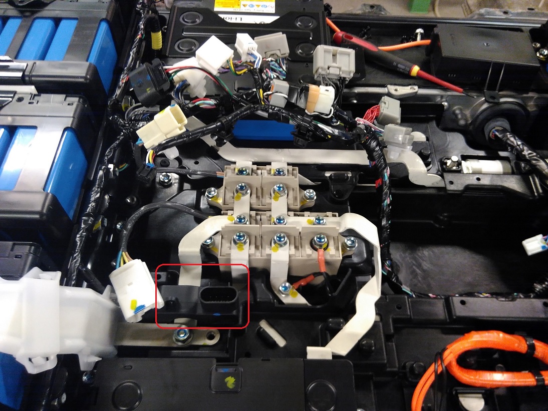
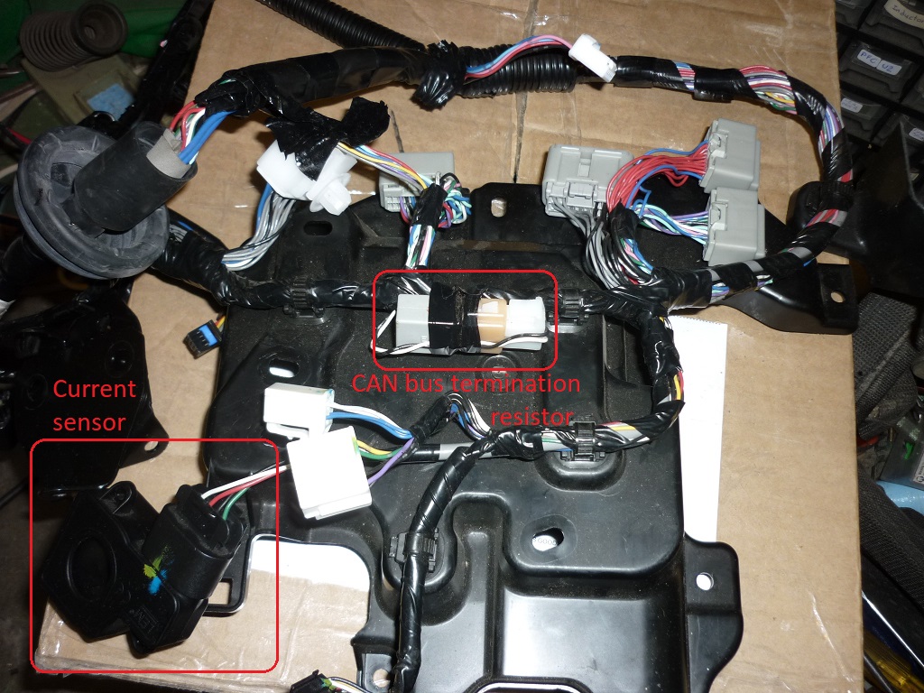
For completeness, here is the location of the sensor in one of the battery teardown photos (thanks, Dani!). It's normally hidden under a plastic cover that holds the five star-point ("dummy") connectors, and the world's largest CAN bus termination resistor.

en39zUu.jpg


This area is located towards the front left of the car. [ Edit: the current sensor is measuring the negative end of the battery, before the main negative contactor. ]

Here is the plastic cover with the termination resistor and current sensor (just dangling as it's removed from the pack):

tClF5a6.jpg


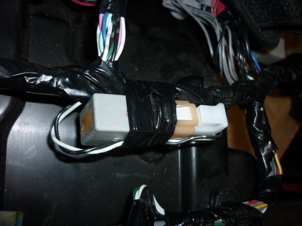
Close-up.

gMs5ED7.jpg


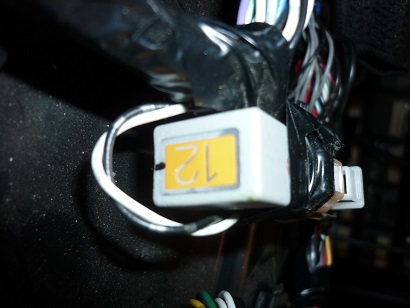
The "12" on the end may indicate 120Ω:

NupL1oH.jpg
 
Thanks for marking the current sensor location; i have looked at Dani's great pack pictures often so that is a big help to identify what's in there.

i've seen the CAN buss termination resistor called out on a FSM wiring diagram, but didn't realize how significant it was. Kinda like adding a large bladder tank to control water hammer in plumbing lines. i guess Mits wanted a big one to let everybody know that they sure-as-hell TERMINATED that thang.
 
coulomb said:
I'm considering modifying the main battery current sensor output to allow use of higher capacity cells in the imiEV battery case.
Would this be a necessary step? I seem to recall that the BMS will slowly recalculate total battery capacity to allow larger capacity cells and that no modifications were necessary.
 
I've been asked to look into this for a company that has done this already, and sees demand for many more if it can be solved. They are using NMC cells, which have a lower voltage characteristic, so the BMS learns a lower capacity that is actually present.

Also, these are 93 Ah cells, and I read somewhere that the limit on this value (or perhaps reporting of this value, it wasn't clear) is limited to 60 Ah.

With 30 km on the GOM, the lowest cell voltage was 3.825 V, meaning that there is still roughly 50% capacity left.

I'd certainly be happy if the BMS will eventually learn a higher capacity, perhaps even something approaching actual capacity, but it doesn't seem likely.

The proper way to solve this would be to modify the BMS to take into consideration the characteristics of the new cells and their initial capacity, but that option doesn't seem open to us. I patch solar inverter firmware, so I'd be prepared to try this, but getting the image to analyse and patch is the problem.

It was pointed out to me that we may have to change the current reported on the CAN bus to other ECUs to prevent other problems. I intend to try a gadget soon that should allow a reduction of measured current by 10-50% (adjustable). I hope that the 10% figure will be noticeable as a range improvement, and if it affects other systems, a 10% change should be noticeable, but hopefully not damaging.

If the digital adjustment is necessary, it would be nice to also adjust the GOM figure, a la Leafs. But I've not seen a CAN Id for the GOM display. Anyone seen one?
 
i had some notes about CAN pids, i think it is pid x346. i haven't verified this personally. Canion reports the RR (GOM) value so it knows the pids to gather the data.

29A: VIN

346: range remaining
373: battery voltage and current
374: SOC
384: heating/cooling current
389: charger current and line voltage
3A4: settings of HVAC console
 
Thanks, Kenny. The can triplet database confirms, but doesn't seem to have the data format. It should be fairly easy to guess given some data. I might even be able to figure it out from some of the published massive CAN data dumps.

[ Edit: this post seems to say that it's the first data byte, so the range of the range meter would be 0-255 km (0 - 158 miles). Hopefully that will be enough :D ]

BTW, does the Range Remaining meter display in miles in North America? I assume that the display processor does the conversion, and the CAN data remains in kilometers.
 
Yes. US I-MiEVs show miles for RR. We’re stuck with 24-hour only clocks, but it does show miles for everything.

I haven’t heard about the 60 Ah limit. Good to know.
 
coulomb said:
...so the range of the range meter would be 0-255 km (0 - 158 miles). Hopefully that will be enough .

Hopefully it won't be enough if you can fit higher capacity cells--don't limit yourself, too much is not enough.
 
Happy New Year Mike, Did you ever find that Sumitomo connector? i know this in an older thread but wanted to bump it too.

Piev Paul is looking for the BMU connectors to make a break-out-box (BOB) and attempt to do a man-in-the-middle (MITM) read and write on the CAN buss to fake out the EV-ECU.
 
Did you ever find that Sumitomo connector
No. The people I was working with changed direction and decided on the CAN bus solution instead, so this connector wasn't needed. Or maybe they found it and it's part of the update kit, but they would not be giving out details about that kit. The kit has a 35-pin very generic looking plug; my guess is that they have a special cable that splits those 35 pins up into various cables to the various car connectors required.

Someone else did the CAN bus work. So sorry, I don't know any of the CAN bus details.
 
Last edited:
No. The people I was working with changed direction and decided on the CAN bus solution instead, so this connector wasn't needed. Or maybe they found it and it's part of the update kit, but they would not be giving out details about that kit. The kit has a 35-pin very generic looking plug; my guess is that they have a special cable that splits those 35 pins up into various cables to the various car connectors required.

Someone else did the CAN bus work. So sorry, I don't know any of the CAN bus details.
Found them.

MX5 series JAE connectors the 26 pin BMU is MX5-26S-C-G

https://www.bmotorsports.com/shop/a...ption=1&keywords=NA+Miata+22+Way+ECU+Plug+Kit
https://www.maxxecu.com/store/engin.../ecu_connector/ecu-connector-mazda-mx5-40-pin
 
Back
Top