coulomb
Well-known member
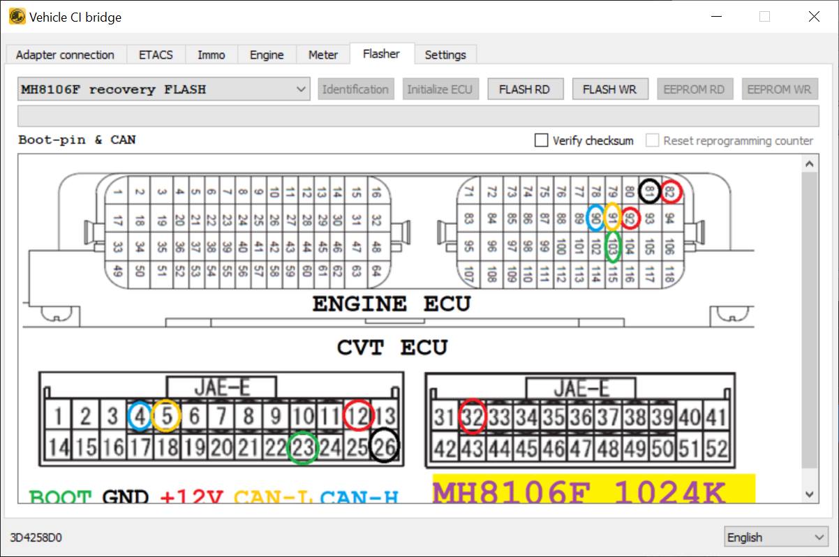
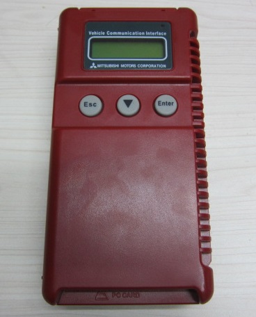
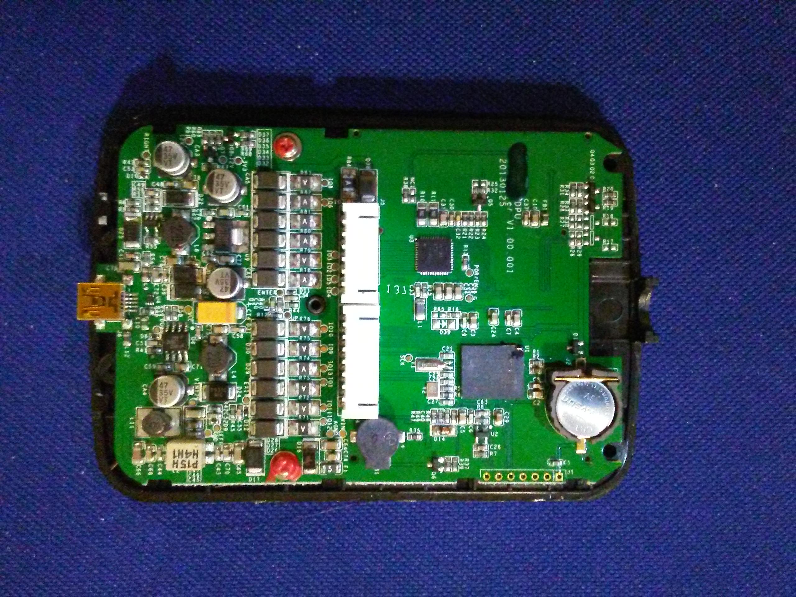
I'm feeling the need to upload some information from my brain to this forum. I'm a noob here, so please direct me to better places to store / discuss this information. I'm chasing some leads on MUT III update files. The MUT III is the Mitsubishi Multi-Use Tester, although MUT perhaps refers to the software rather than the machine itself. It seems to be the way that all Mitsubishi cars and trucks interface the various ECUs with a computer, for reading and clearing error codes, updating firmware, and much else. There are CDs with install files that go on the computer, and it seems that some of these, the .CFF files, may contain firmware for the various ECUs, such as the BMU, CMUs, and the charger. Unfortunately, my data source is not terribly reliable, and I only have firmware files at present for the BMU, MY 2010 and MY 2011.
The charger and CMUs use totally different microcontrollers, though both are 32-bit Renesas RISC processors. Thanks to forum member @Kiev, we know what these processors are.
The On Board Charger seems to use this microcontroller: R5F71424AK64FPV . Kiev called it a R5F71424FPV (edit: missing the AK64 part), but that may be a shortened code to fit on the actual chip. The core is a member of the Super H RISC family, apparently SH-2. It's a member of the SH-7147 group.
Hardware manual, software manual.
This is a traditional RISC CPU, with a fixed 16-bit instruction length, delay slots, and not even traditional immediate addressing modes. To load an immediate value, you reference a constant relative to the PC. To call a function, you need to load that immediate constant with one instruction, and call with another. The return instruction is RTS. I use the return instruction, a moderately common one, as a sort of sanity test for firmware files. The opcode seems to be 000B. There are 16 general purpose registers.
The CMUs [ edit: was BMU] seem to use a V850F3612 microcontroller. I'll presume that this is a member of the V850ES family, even though I can find few manuals for it.
V850 family. V850 family architecture.
[ Edit: see this post about ⅔ down for better CMU manuals. ]
This is a more friendly (to the reverse engineer) processor. It has a mixture of 16 and 32-bit instructions, no delay slots, and 32 general purpose registers. The return from subroutine instruction seems to be the JMP instruction (!), with a binary opcode of 0000 0000 011r rrrr. I don't know what register is used to pass the return address. Initially I thought it was the link pointer register (r31), but this seems be be more of a base register (like ebp in the x86 architecture). Not knowing the register used, there are about 26 reasonable values, and none that I tried seem to occur frequently enough to indicate that I've found instructions in the .CFF files.
[ Edit: I've since found out that most (but not all!) functions use the link register for returning, but they mostly (not always!) use the dispose instruction, which pops registers, adjusts the stack pointer to deallocate locals, and performs the indirect branch (to actually do the return) all in one instruction. There is a corresponding prepare instruction to push registers and adjust the stack pointer (to allocated local variables). The opcode for the dispose instruction is a bit sparse, but a common pattern is 42 06 (with the 06 being the most significant byte). ]
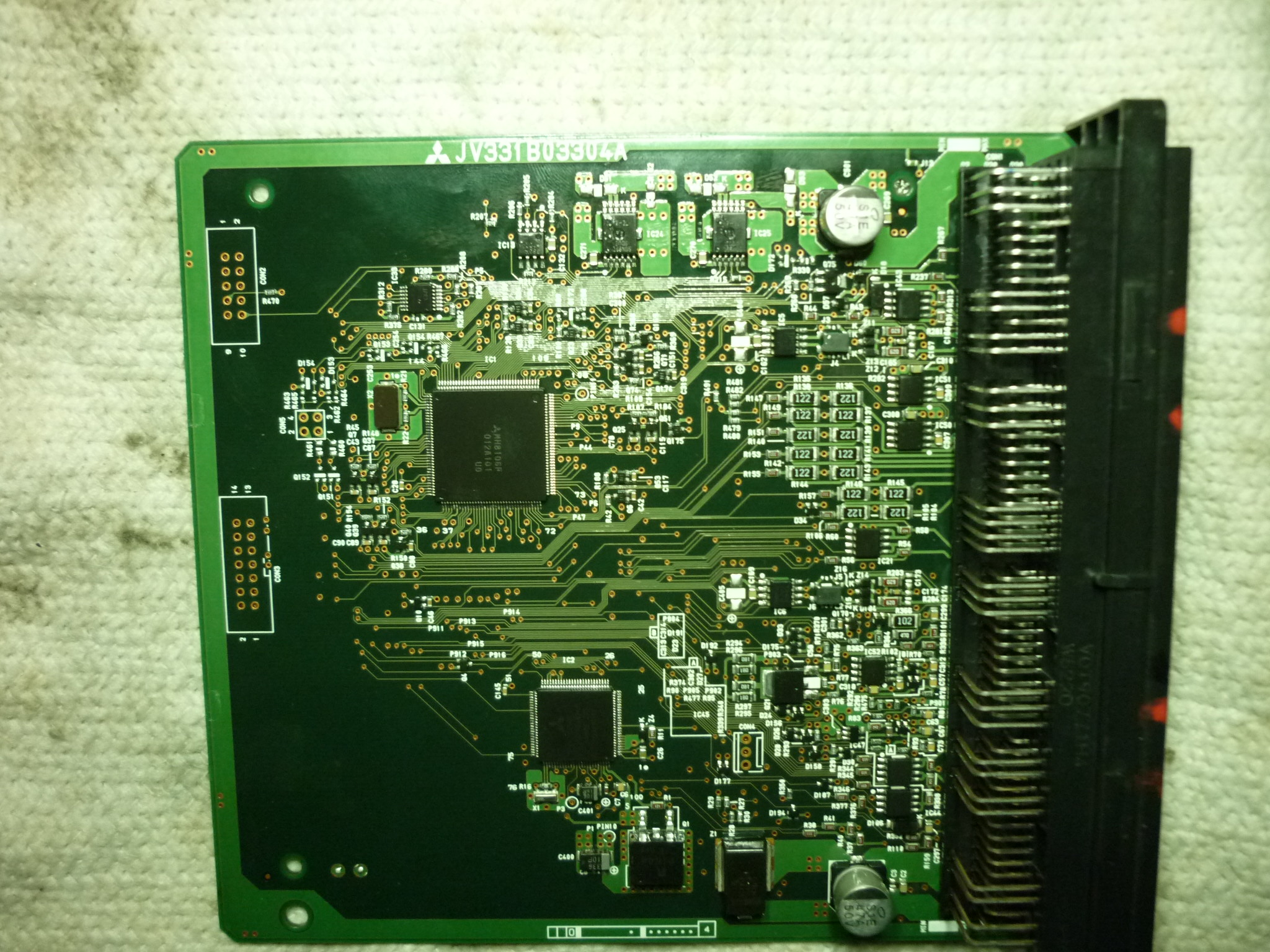
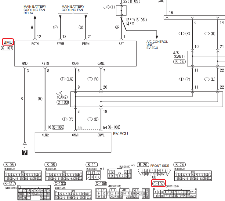
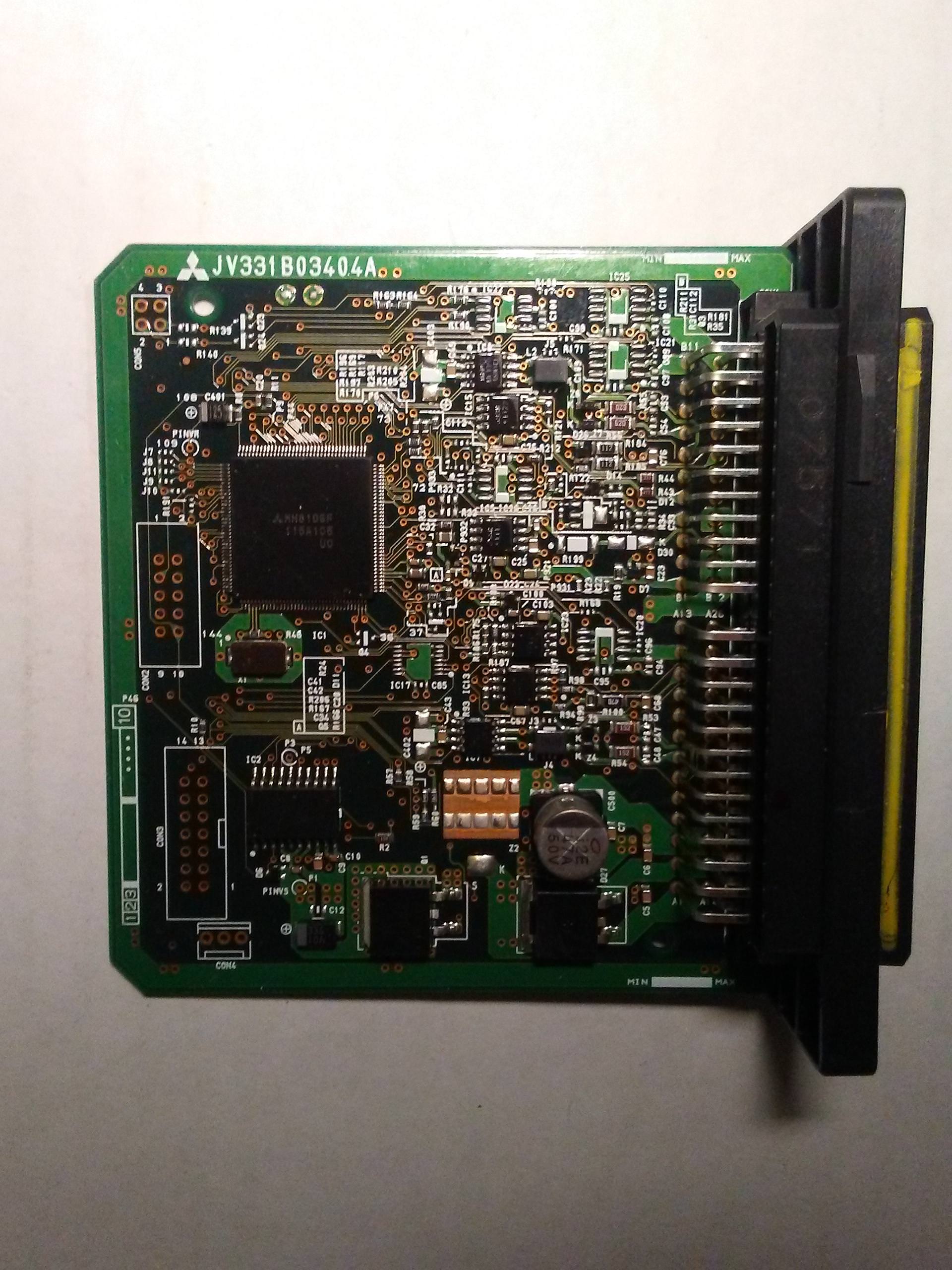
The BMU uses MH8106F, 144 pins (see post below). Unfortunately, little seems to be known about this processor, though various vendors seem to offer ECU updates. They may be part of the M32r series, per this page.
So now the bad news. CFF seems to stand for Common File Format. [ Edit: It may stand for Controller Firmware Files or Caesar Flash Format. There are files like CAESARCOMPDB in the install image. ] Common File Format seems very general. They all start with a bunch of text, including the author's name, various paths to files, but after a few kilobytes of that, it's all binary and no text at all. I tried disassembling a few files that had iMiev and BMU in them with both of the above microcontrollers, and nothing made any sense.
This could be due to many reasons. One, the CFF files might not actually contain the firmware that gets downloaded over the CAN bus into the charger or BMU, as I've been assuming. Two, the business end of the CFF files might be encrypted. There is talk on some forums about requiring passwords to use certain MUT III functions. Maybe the password is needed to decrypt the back end of the .CFF files. To me, the CFF files don't look random enough to be encrypted, but that's just a gut feeling. Three, I'm possibly overlooking something, like endianness issues.
The hope is that these files will allow reverse engineering of how the ECUs work, so that poorly documented trouble codes can be better understood, and perhaps, perhaps, firmware might be able to be patched to modify behavior. In particular, it may be possible to overcome VIN locking and other practices that make life miserable for people trying to maintain their vehicles and not be at the mercy of the manufacturer. Later, it may even be possible to change some performance limits, such as the motor power limit. But that's way in the future.
Edit: I've just realised that I have been confusing BMU and CMU (Battery Management master Unit, and the Cell Monitoring Units). There is probably yet another processor used in the CMUs, different from the other two, and that will likely explain the present lack of success. So the V850F3612 microcontroller is from the CMUs, not from the BMU. @Kiev, or anyone else, do you know the microcontroller used in the BMU?
Edit 2: I believe that I have a charger firmware file now. But it also makes no sense so far.
Edit 3: Added small paragraph about BMU processor.
The charger and CMUs use totally different microcontrollers, though both are 32-bit Renesas RISC processors. Thanks to forum member @Kiev, we know what these processors are.
The On Board Charger seems to use this microcontroller: R5F71424AK64FPV . Kiev called it a R5F71424FPV (edit: missing the AK64 part), but that may be a shortened code to fit on the actual chip. The core is a member of the Super H RISC family, apparently SH-2. It's a member of the SH-7147 group.
Hardware manual, software manual.
This is a traditional RISC CPU, with a fixed 16-bit instruction length, delay slots, and not even traditional immediate addressing modes. To load an immediate value, you reference a constant relative to the PC. To call a function, you need to load that immediate constant with one instruction, and call with another. The return instruction is RTS. I use the return instruction, a moderately common one, as a sort of sanity test for firmware files. The opcode seems to be 000B. There are 16 general purpose registers.
The CMUs [ edit: was BMU] seem to use a V850F3612 microcontroller. I'll presume that this is a member of the V850ES family, even though I can find few manuals for it.
V850 family. V850 family architecture.
[ Edit: see this post about ⅔ down for better CMU manuals. ]
This is a more friendly (to the reverse engineer) processor. It has a mixture of 16 and 32-bit instructions, no delay slots, and 32 general purpose registers. The return from subroutine instruction seems to be the JMP instruction (!), with a binary opcode of 0000 0000 011r rrrr. I don't know what register is used to pass the return address. Initially I thought it was the link pointer register (r31), but this seems be be more of a base register (like ebp in the x86 architecture). Not knowing the register used, there are about 26 reasonable values, and none that I tried seem to occur frequently enough to indicate that I've found instructions in the .CFF files.
[ Edit: I've since found out that most (but not all!) functions use the link register for returning, but they mostly (not always!) use the dispose instruction, which pops registers, adjusts the stack pointer to deallocate locals, and performs the indirect branch (to actually do the return) all in one instruction. There is a corresponding prepare instruction to push registers and adjust the stack pointer (to allocated local variables). The opcode for the dispose instruction is a bit sparse, but a common pattern is 42 06 (with the 06 being the most significant byte). ]
The BMU uses MH8106F, 144 pins (see post below). Unfortunately, little seems to be known about this processor, though various vendors seem to offer ECU updates. They may be part of the M32r series, per this page.
So now the bad news. CFF seems to stand for Common File Format. [ Edit: It may stand for Controller Firmware Files or Caesar Flash Format. There are files like CAESARCOMPDB in the install image. ] Common File Format seems very general. They all start with a bunch of text, including the author's name, various paths to files, but after a few kilobytes of that, it's all binary and no text at all. I tried disassembling a few files that had iMiev and BMU in them with both of the above microcontrollers, and nothing made any sense.
This could be due to many reasons. One, the CFF files might not actually contain the firmware that gets downloaded over the CAN bus into the charger or BMU, as I've been assuming. Two, the business end of the CFF files might be encrypted. There is talk on some forums about requiring passwords to use certain MUT III functions. Maybe the password is needed to decrypt the back end of the .CFF files. To me, the CFF files don't look random enough to be encrypted, but that's just a gut feeling. Three, I'm possibly overlooking something, like endianness issues.
The hope is that these files will allow reverse engineering of how the ECUs work, so that poorly documented trouble codes can be better understood, and perhaps, perhaps, firmware might be able to be patched to modify behavior. In particular, it may be possible to overcome VIN locking and other practices that make life miserable for people trying to maintain their vehicles and not be at the mercy of the manufacturer. Later, it may even be possible to change some performance limits, such as the motor power limit. But that's way in the future.
Edit: I've just realised that I have been confusing BMU and CMU (Battery Management master Unit, and the Cell Monitoring Units). There is probably yet another processor used in the CMUs, different from the other two, and that will likely explain the present lack of success. So the V850F3612 microcontroller is from the CMUs, not from the BMU. @Kiev, or anyone else, do you know the microcontroller used in the BMU?
Edit 2: I believe that I have a charger firmware file now. But it also makes no sense so far.
Edit 3: Added small paragraph about BMU processor.
")