The Troubleshooting and Repair for On-board Charger (OBC) Thread

Mitsubishi i-MiEV Forum

Help Support Mitsubishi i-MiEV Forum:

This site may earn a commission from merchant affiliate links, including eBay, Amazon, and others.
Hello together,
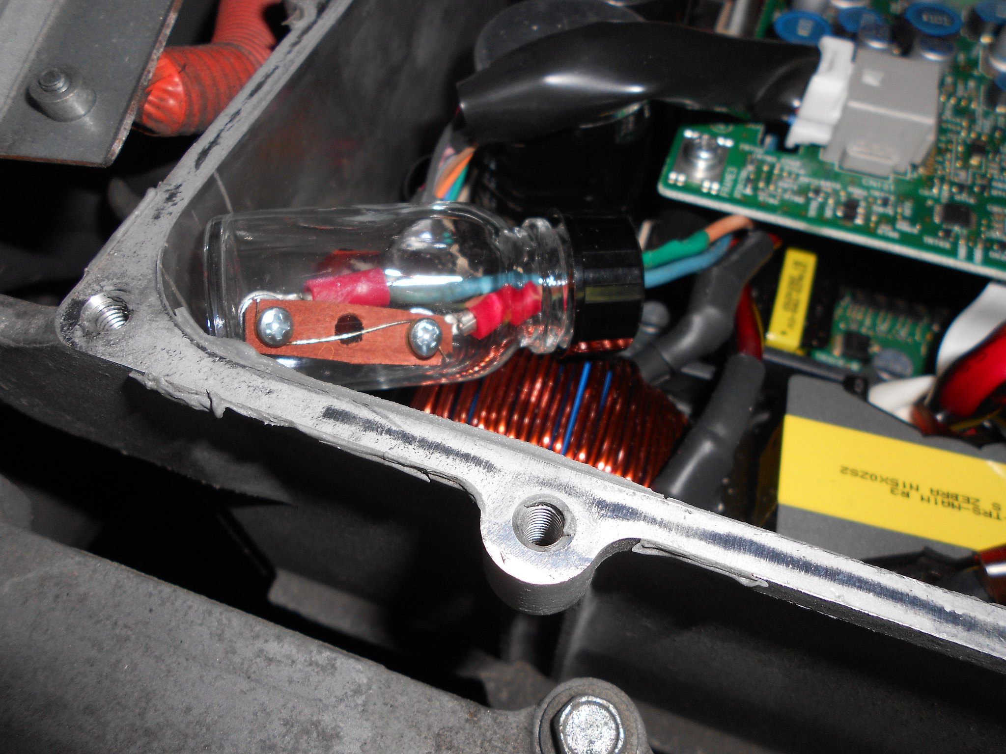
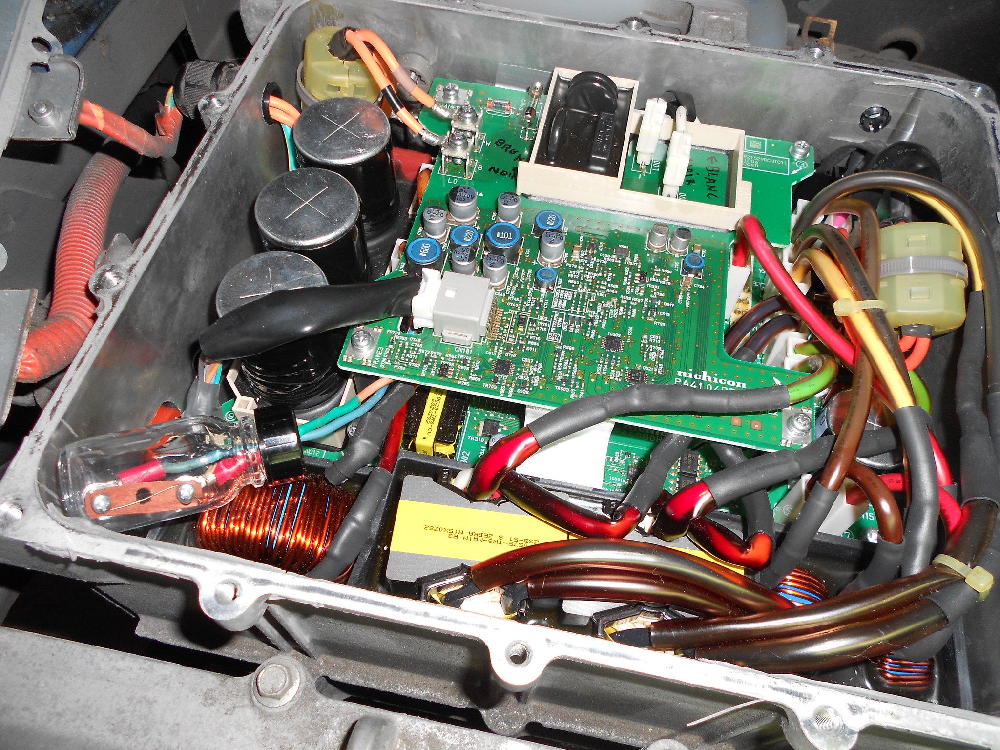
I have the charging problem with my IMIEV. After plugging in the power cable for the 16A charge I can hear a fan spinning for only one second and after about 5 seconds the light on the charger turns off. The cable to the car has been tested and is working. The 20A fuse is fine and the OBC does look good at first sight and has already been replaced by a used one where I can not verify if it is working. The blue caps are good as well as the two fuses inside the OBC.
I can turn the car on and it jumps to ready but does not charge the 12V battery. Fast charge does work. The yellow car with the exclamation mark lights up. My only error code is P1A12. I can not hear any relays clicking and the 12V battery is new.
Does anyone have any suggestions on where to go from there?

Thank you so much!
 
You didn't say what year is your car; if 2012 then there is an internal 2-digit code that would indicate what is the fault, unfortunately it requires a MUT to see those codes; if 2017 then there would be another DTC P-code that would indicate the specific fault in the OBC/DC Converter.

Since it appears to affect both the OBC and the DCC, i might suspect the 12V hot all the time wire that supplies both devices; or the fuse in the MCU; or the wiring harness between the MCU and the OBC.

When is it that you don't hear any relays--during charging? The car runs and drives, goes to READY okay?
 
My car is from 2011. I unfortunately do not have a MUT but my dealer said that the car can not connect to the OBC. I am not sure if this is true.

I checked the fuse on the right bottom under the cover at the device right next to the OBC. I hope this is the correct one.

I can hear three realay clicks in the front of the car when plugging in the cable and after two or three seconds again three clicks. I am not sure if I hear any clicks in the OBC at least not an obvious one.

The car goes to Ready and is able to drive. The yellow car and the red battery light stay on while driving.

How would you check the 12V hot? When the PCBs are in the car? Does the harness only consist of the one cable going over to the MCU and can I just check the two wires for continuity?

I measured the voltage between the to srewed in cables in the OBC when plugging in the charger. There are 235V for like three seconds then it goes down to 0. I can read the same voltage across the black and white cable connecting the two PCBs. The orange cable from the OBC to the MCU measures 0V. When plugging in the cable the 12V battery drops from 13V to 12.8V.
 
It sounds like the AC is getting to the OBC, so the EVECU is working properly to engage the contactors/relays for the pack, and the signal is sent to the EVSE to connect the mains.

Have you inspected the bottom control board for the white ceramic resistors and input AC filter capacitor in the fenced area of black potting?

For completeness i would recommend to pull, check and clean the contacts of all the little fuses and relays up front under the hood, and inspect wiring harnesses for rodent damage. Just to rule out simple things if you don't find damaged parts within the OBC.

Maybe there are 2 failures and the OBC and DCC are not related.

What is your skill and confidence level with electrical and electronics repairs? What do you have for multimeter and probes, etc.
 
I just checked all fuses and relays in the front, they seem to be fine. My local repair shop already tried to replace the wireing harness without success.

I took a look at the board and it looks like new. Is there any way of measureing the resistors without removing the bottom board?

I also looked very closely if there are any SMD parts broken off but did not find one.

I am pretty confident with electronic repairs. I have a multimeter, DC power suppy, DC electronic load, oscilloscope, soldering station, hot air soldering station, desoldering station, thermal camera and microscope.
 
okay great, sounds like you are set.

Check continuity between the top edge black wire terminal marked "B" to the waffle plate upper left top junction marked "L".

You can measure if the resistors are okay from the white terminal on the top edge marked "W" to the waffle plate quad solder junction marked "N", should read 9.7 Ohms if the ceramics and fuse is okay.

Next check the relay with a 5V supply at Diode D301, you can search this thread for how others have connected and tested it. When engaged it will bypass the resistors so the resistance reading should go to zero.

After this it is time to check the diode drops in the waffle plate. That is shown several times in this thread.
 
kiev said:
The main controller chip, IC701, looks to have some surface distress? Maybe damage or just marked up thru the conformal coating?
Just conformal coating.

So far car is charging fine.
 
Sorry for the late reply. I do have continutity between between B and L. I measured the resistors and have indeed an open circuit there. So for my understanding at least one of the resisitors is dead. I would now remove the bottom PCB from the OBC and desolder the waffle plate and scrape out the potting around the resistors. Is there anything I should check and measure while the PCB is still inside the car?
 
One of those resistors has an internal fuse.

i can't think of anything else to measure while in place.

My theory is that the resistors blow if/when the little black relay gets de-energized or fails to energize. But what was the cause of that? Possibly trying to charge with a weak or old 12V battery; or some other sudden interruption of the low voltage supply.

How does that affect the DC/DC Converter failure? A sudden interruption of the HVDC or the LV supply during operation might also cause a failure.

Possibly the DCC failed first, which caused a sudden dropout or surge on the 12V buss, which then caused the AC relay to open while charging at full power. This would explain how 2 failures might occur.

There is a 5V regulator chip on the DCC that we have seen fail. The DCC board can be accessed under the bottom cover while the OBC is mounted in the car, but it might be easier to drain the coolant and remove the box, you will have to evaluate it for your situation.

After you replace the resistors then charging should be possible again, and if you externally charge the 12V then the car should go to READY and could be used temporarily.

There is a separate thread for the DC Converter troubleshooting with the technical details and schematics of that board. Eldenh drove his car with a failed DCC for several months using a lithium 12V. i'm not sure that we have ever had a successful repair of a DCC board.
 
Thank you for your long answer. I removed the waffle plate today, scraped out the potting and desoldered the two resisitors. This was very difficult to do and took me a very long time. The smaller of the two resistors is indeed dead without any obvious sign from the outside. It looks like new.

I would like to change out the resistor first to see if I can charge again. At the same time I think it would be a good idea to change out the blue caps even if they are fine. Do you have prefered replacement parts for this or should I just buy the ones easaly available for me?
 
That's a good idea, see if charging will work with a new resistor first before tearing into the DCC.

For the snubber caps, you just have to get whatever you can find in stock , a higher voltage rating is a better cap for these purposes. Take a look at Simon's repair (forum handle: dbmandrake) for a great example with 3kV caps.
 
I had the same problem.
The ceramic of the small R106 was broken due to over heating.
The thermal fuse in the R105 did blow off at 157 °C but luckily R106 and R105 resistors were safe.

I fixed back the problem with a 20A fuse .... easily accessible now and the On-board charger is working again.

My external charger is a 16A, 250V.

Do you think it would be safer to use a lower amperage external charger?

In other words, in the US you are using 110 Volt external charger.
Less problems in the US should occur with the On-board Charger (OBC).

The shut down of my Peugeot iOn On-board charger happened around 60 % of Soc during a charge in the night.
Not like some peoples, I never stopped a charge before it stopped by itself at 100 %.
At this time there was some electrical shut down. As it took me a long time before I realise I will not be able to charge, I cannot remember if a shut down happened at this particular night. At this time, for me, the charge stopped at 60% because of a cell equilibrium problem, so I even went down at one bar to recalibrate the battery...
It would have been wise to check my auxiliary battery voltage but at that time I was not aware about the importance it could have.
Also, when the main battery is on charge, the auxiliary battery is also on charge.

The car is nearly ten years old with 80 000 km and the auxiliary battery have the same age.
Battery capacity is of 35.5 Ah, Normandy temperate weather is appreciated by batteries.

Inscriptions on the Thermal fuse " LE 152 157°C TAM 15A 250V PSE 106 JET "

@+
 
Howdy BlueL. Welcome to the forum and thanks for sharing your repair.

i don't think it would matter what voltage or current is used.

The OBC has to boost whichever mains voltage is used, so more boost is needed when using 120vac.

The OBC was designed to handle the rated current with normal margins in the component selections, and i'm not aware of any reported overcurrent failures that point to a design defect.

At 10 years old, you might consider if it is time to invest in a new auxiliary battery before it fails and potentially causes an expensive fault. It would be interesting to load test the aux battery to measure the capacity.
 
Thanks for your answer

Also many thanks for this blog and all the contributors.
I would not have been able to fix my OBC without your precious informations.

The resistors R105 and R106 being now "naked", to avoid any electrical contact, I inserted some glass plates.
Glass plates should also help in case of some heat excursion.
Domino bars are used for electric connections.

The fuse in the glass bottle is a 20A, it might be too much.

@+

1 DSCN1960 by Blue I.ightning, sur Flickr

2 DSCN1983 by Blue I.ightning, sur Flickr

3 DSCN1994 by Blue I.ightning, sur Flickr

3 DSCN2005 by Blue I.ightning, sur Flickr

4 DSCN1998 by Blue I.ightning, sur Flickr

4 DSCN2012 by Blue I.ightning, sur Flickr

5 DSCN2010 by Blue I.ightning, sur Flickr

5 DSCN2018 by Blue I.ightning, sur Flickr

6 DSCN2019 by Blue I.ightning, sur Flickr

8 DSCN2021 by Blue I.ightning, sur Flickr

9 DSCN2022 by Blue I.ightning, sur Flickr

 
BlueLightning said:
The fuse in the glass bottle is a 20A, it might be too much.
The fuse in the resistor is a thermal fuse. Obviously, it needs to be in thermal contact with the resistor element.

I don't think that your fuse will protect much, but it should not do any harm. Fortunately, it should only be blocking AC; you'd have yourself an arc lamp if it was blocking pack voltage (DC).

Long term, the fuse wire will likely fatigue from the pulses of over-current (peaks of around 36 A). But the RMS current should be around 25 A, quickly reducing in amplitude. But I assume that this is not the long-term fix :D
 
Hello, everyone

Today 12.30 Click, click he's loading !! .. and the sun comes out. :D :lol: :D :lol:

Here is an excerpt from my photo documentation.
I left out the potting compound.
This is mainly used to protect tall components from vibration.
I fixed these components in some other way with the green adhesive.

https://postimg.cc/gallery/R3cMjJ1

With sunny greetings from Germany
siggs
 
Great photos, thanks for sharing your repair and showing how to replace these components from above without removing the waffle plate.

Was there any metal splatter or debris on the bottom of the control board due to the blue snubber capacitor failure?
 
Hello, kiev

There was a black area on the back of the upper board, caused by the blown blue snubber.
In the gap between the lower board and the waffelplate, everything seemed clean,
as well as the epoxy surface of the waffelplate.

With sunny greetings from Germany
siggs
 
Hello, kiev

Forgot:
New blue snubber are 3KV.
New ceramic resistors are 10 watt.

With sunny greetings from Germany
siggs
 
Well done siggs

P on the scheme is 5 W.
Is 10 W better ?

P=RI^2 Or P=U^2/R

10 W
4.7 Ohm then Imax = 1.5 A, or Umax = 6.9 V

5 W
4.7 Ohm then Imax = 1.0 A, or Umax = 4.9 V

No thermal fuse ?
 
Back
Top