Firmware for charger, BMU, CMUs

Mitsubishi i-MiEV Forum

Help Support Mitsubishi i-MiEV Forum:

This site may earn a commission from merchant affiliate links, including eBay, Amazon, and others.

coulomb

Well-known member
Joined
Jun 10, 2018
Messages
527
Location
Brisbane, Australia
I'm feeling the need to upload some information from my brain to this forum. I'm a noob here, so please direct me to better places to store / discuss this information. I'm chasing some leads on MUT III update files. The MUT III is the Mitsubishi Multi-Use Tester, although MUT perhaps refers to the software rather than the machine itself. It seems to be the way that all Mitsubishi cars and trucks interface the various ECUs with a computer, for reading and clearing error codes, updating firmware, and much else. There are CDs with install files that go on the computer, and it seems that some of these, the .CFF files, may contain firmware for the various ECUs, such as the BMU, CMUs, and the charger. Unfortunately, my data source is not terribly reliable, and I only have firmware files at present for the BMU, MY 2010 and MY 2011.

The charger and CMUs use totally different microcontrollers, though both are 32-bit Renesas RISC processors. Thanks to forum member @Kiev, we know what these processors are.

The On Board Charger seems to use this microcontroller: R5F71424AK64FPV . Kiev called it a R5F71424FPV (edit: missing the AK64 part), but that may be a shortened code to fit on the actual chip. The core is a member of the Super H RISC family, apparently SH-2. It's a member of the SH-7147 group.

Hardware manual, software manual.

This is a traditional RISC CPU, with a fixed 16-bit instruction length, delay slots, and not even traditional immediate addressing modes. To load an immediate value, you reference a constant relative to the PC. To call a function, you need to load that immediate constant with one instruction, and call with another. The return instruction is RTS. I use the return instruction, a moderately common one, as a sort of sanity test for firmware files. The opcode seems to be 000B. There are 16 general purpose registers.

The CMUs [ edit: was BMU] seem to use a V850F3612 microcontroller. I'll presume that this is a member of the V850ES family, even though I can find few manuals for it.
V850 family. V850 family architecture.
[ Edit: see this post about ⅔ down for better CMU manuals. ]

This is a more friendly (to the reverse engineer) processor. It has a mixture of 16 and 32-bit instructions, no delay slots, and 32 general purpose registers. The return from subroutine instruction seems to be the JMP instruction (!), with a binary opcode of 0000 0000 011r rrrr. I don't know what register is used to pass the return address. Initially I thought it was the link pointer register (r31), but this seems be be more of a base register (like ebp in the x86 architecture). Not knowing the register used, there are about 26 reasonable values, and none that I tried seem to occur frequently enough to indicate that I've found instructions in the .CFF files.

[ Edit: I've since found out that most (but not all!) functions use the link register for returning, but they mostly (not always!) use the dispose instruction, which pops registers, adjusts the stack pointer to deallocate locals, and performs the indirect branch (to actually do the return) all in one instruction. There is a corresponding prepare instruction to push registers and adjust the stack pointer (to allocated local variables). The opcode for the dispose instruction is a bit sparse, but a common pattern is 42 06 (with the 06 being the most significant byte). ]

The BMU uses MH8106F, 144 pins (see post below). Unfortunately, little seems to be known about this processor, though various vendors seem to offer ECU updates. They may be part of the M32r series, per this page.

So now the bad news. CFF seems to stand for Common File Format. [ Edit: It may stand for Controller Firmware Files or Caesar Flash Format. There are files like CAESARCOMPDB in the install image. ] Common File Format seems very general. They all start with a bunch of text, including the author's name, various paths to files, but after a few kilobytes of that, it's all binary and no text at all. I tried disassembling a few files that had iMiev and BMU in them with both of the above microcontrollers, and nothing made any sense.

This could be due to many reasons. One, the CFF files might not actually contain the firmware that gets downloaded over the CAN bus into the charger or BMU, as I've been assuming. Two, the business end of the CFF files might be encrypted. There is talk on some forums about requiring passwords to use certain MUT III functions. Maybe the password is needed to decrypt the back end of the .CFF files. To me, the CFF files don't look random enough to be encrypted, but that's just a gut feeling. Three, I'm possibly overlooking something, like endianness issues.

The hope is that these files will allow reverse engineering of how the ECUs work, so that poorly documented trouble codes can be better understood, and perhaps, perhaps, firmware might be able to be patched to modify behavior. In particular, it may be possible to overcome VIN locking and other practices that make life miserable for people trying to maintain their vehicles and not be at the mercy of the manufacturer. Later, it may even be possible to change some performance limits, such as the motor power limit. But that's way in the future.

Edit: I've just realised that I have been confusing BMU and CMU (Battery Management master Unit, and the Cell Monitoring Units). There is probably yet another processor used in the CMUs, different from the other two, and that will likely explain the present lack of success. So the V850F3612 microcontroller is from the CMUs, not from the BMU. @Kiev, or anyone else, do you know the microcontroller used in the BMU?

Edit 2: I believe that I have a charger firmware file now. But it also makes no sense so far.
Edit 3: Added small paragraph about BMU processor.
 
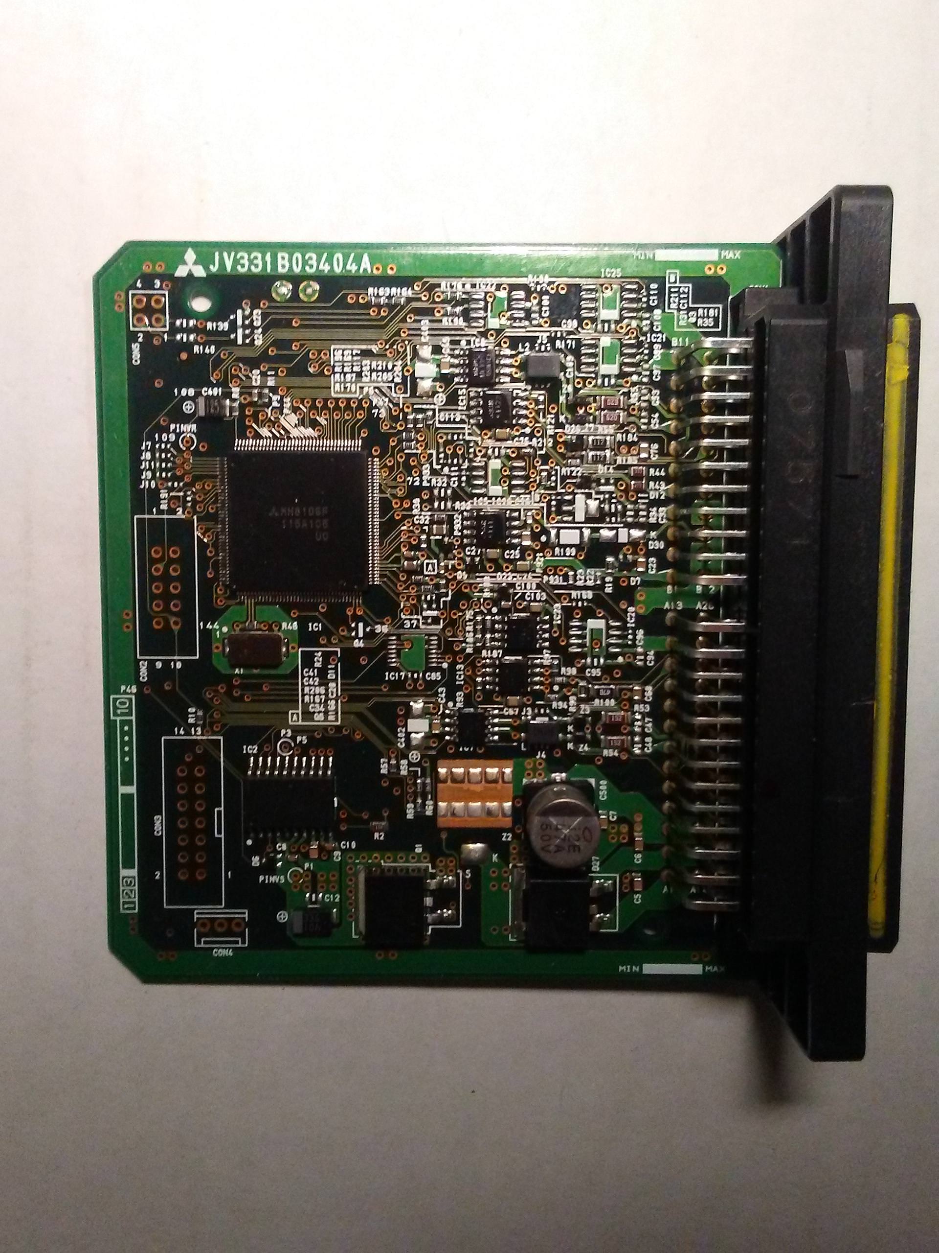
Here is a quick shot of the 2012 BMU board.

There are several empty thru-hole connector slots, possibly for JTAG and eeprom? programming

IC1 is Mitsubishi MH8106F 115A105 U0, 144-pins

IC2 is 20-pin 2338A1 SKA [TRIANGLE MARK] 1917 1917C00MDA

zAsonlX.jpg
 
I need to upload again; please pardon the stream of consciousness.

I was browsing the 2018 MUT-III DVD I found in a torrent. The main executable seems to be MUT3_SE.exe (MultiUseTester three Second Edition). Someone pointed me to the second edition for iMievs; thanks. It and its dozen or so DLLs (Dynamic Link Libraries) are .NET assemblies. That means they decompile nicely; I use the free and very useful JetBrains dotPeek. MutVciUpdate.dll contains the class FirmwareUpdate, which has functions like Download(). It calls functions like this.m_FirmWareControl.EraseSector() and this.m_FirmWareControl.Update(). Along the way, there are functions:
* this.m_FirmWareControl.GetDataOffset()
* this.m_FirmWareControl.GetDataByteLen(), and
* this.m_FirmWareControl.GetDataRecord()
which pull important numbers from the .RPG file.

I've been looking at the .CFF files so far, but someone mentioned that the .RPG files are also important. So this looks good. [ Edit: it turned out to be no use, at least for the RPG files available so far, for iMiev related firmware; see this post. ]

In the RPG file, the first two bytes (little endian) are the number of "fields" of various kinds. Each field record is a fixed length (usually 6), which is in the next 2 bytes. Then follows an array of three 16-bit words, with "id code", "offset", and "size". The important id codes are:
* 01 20 for DataOffset (big endian, 2 bytes)
* 02 30 for DataByteLen (big endian, 4 bytes)
* 03 30 for DataRecord (big endian, 4 bytes) (number of records, which seem to be the number of flash segments).
These three starred fields are read by the three starred functions mentioned above.
Possibly important:
* 02 20 for Pass (password?). Typically 5 bytes; seen values of 85 0 0 0 0, 92 0 0 0 0, and 10 0 0 0 0 (all hex).

For the .RPG files I looked at, DataOffset was always 0x203, the DataByteLen was always 0x400 (=1024), and the DataRecord was around 0xEE (238) to 0xF0 (240). So these files contained about 240 KiB (Kibibytes, 1024 bytes) of actual data.

At the DataOffset is a 0x3A (ascii colon), followed by what appears to be an big endian 8-byte address. This is followed by the DataByteLen bytes of actual flashable data, and this triplet (colon, address, data) repeats DataRecord times. In the RPG files I examined, the addresses of flashable data ranged from 0x200000 to often 0x23BC00 (ending at one less than 0x23C000).

The first two bytes of data have so far always been 0x55 0xAA, which looks like a "tag" indicating program presence. Soon after, in ascii, comes the name of the file (e.g. "00E08114" for file VE08114.RPG, and what appears to be a version number, like "2.02", followed by a several bytes of 0x20 (ascii spaces). Next is a string like "20081215", which suggests the date 2008/Dec/15. Even more spaces follow, then many FFs.

After a block of FFs (several flash sectors), there follows what looks like a set of addresses or vectors, the some random-looking bytes that could well be code. In this last random looking section, there are 0B 00 sequences often enough to suggest the end of subroutines. (As mentioned in my first post, the RTS instruction of the SH-2 family, as used in the charrger, has an opcode value of 000B, which might be represented in little endian form as 0B 00.

I'll write a small program to extract the binary data next, and attempt to disassemble it. Unfortunately, I can't see the word "miev" in any RPG files, and the years seem wrong, but I think I'm making progress.
 
coulomb said:
I'll write a small program to extract the binary data next, and attempt to disassemble it.
Source code for a very simple console mode C program is here. Compile with GCC for Cygwin or similar.

So I've gotten an RPG image to disassemble, and it's not what I had hoped for. This seems to be the firmware for the VCI, the dongle that sits between the PC and the vehicle:

bQEq9xB.jpg


It happens to use a similar processor to the CMU, though there seem to be a few differences. But there seems to be a way of getting firmware to to (e.g.) the ECU, since there are text strings like "ECU same as VCI ". I assume that means that whatever firmware image is downloaded to the VCI, it's the same version as the ECU has now, so there is no point flashing it again. Hopefully I'll get to where those images come from.

Edit: it looks like all the VE*.RPG files are firmware for various models and revisions of the VCI.
Edit: BMU -> CMU again. Sigh.
 
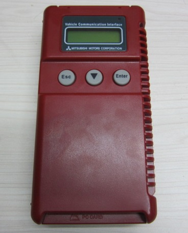
Is there anyone who owns a MUT-III VCI (Lite or not), who is prepared to open up their unit? It would really help me to know the exact processor that they use. In other words, please tell me all the numbers and letters printed on the big chip on the CPU board. Renesas make of the order of a hundred CPUs, and Google doesn't seem to search their PDF files, or if they do, I can't find the right keywords to get what I want. I tried guessing a model and downloading the manual for that, and it wasn't even close. I realise now I've been very lucky that the processor in the VCI is so similar to the one in the BMU, but there are differences that mean that hundreds of memory references are completely opaque to me. With a manual for the right processor, all these would instead become valuable clues about what the bits of code are doing.

Thanks in advance.

Ooh - I just realised, from the few photos that I can find on the web, that the main CPU may not be visible without taking out a board on top of the CPU board. That seems like a big risk, so don't do it if you're not confident with electronics. I certainly don't want to put people out of pocket by hundreds of dollars, for some undefined possible future benefit.
 
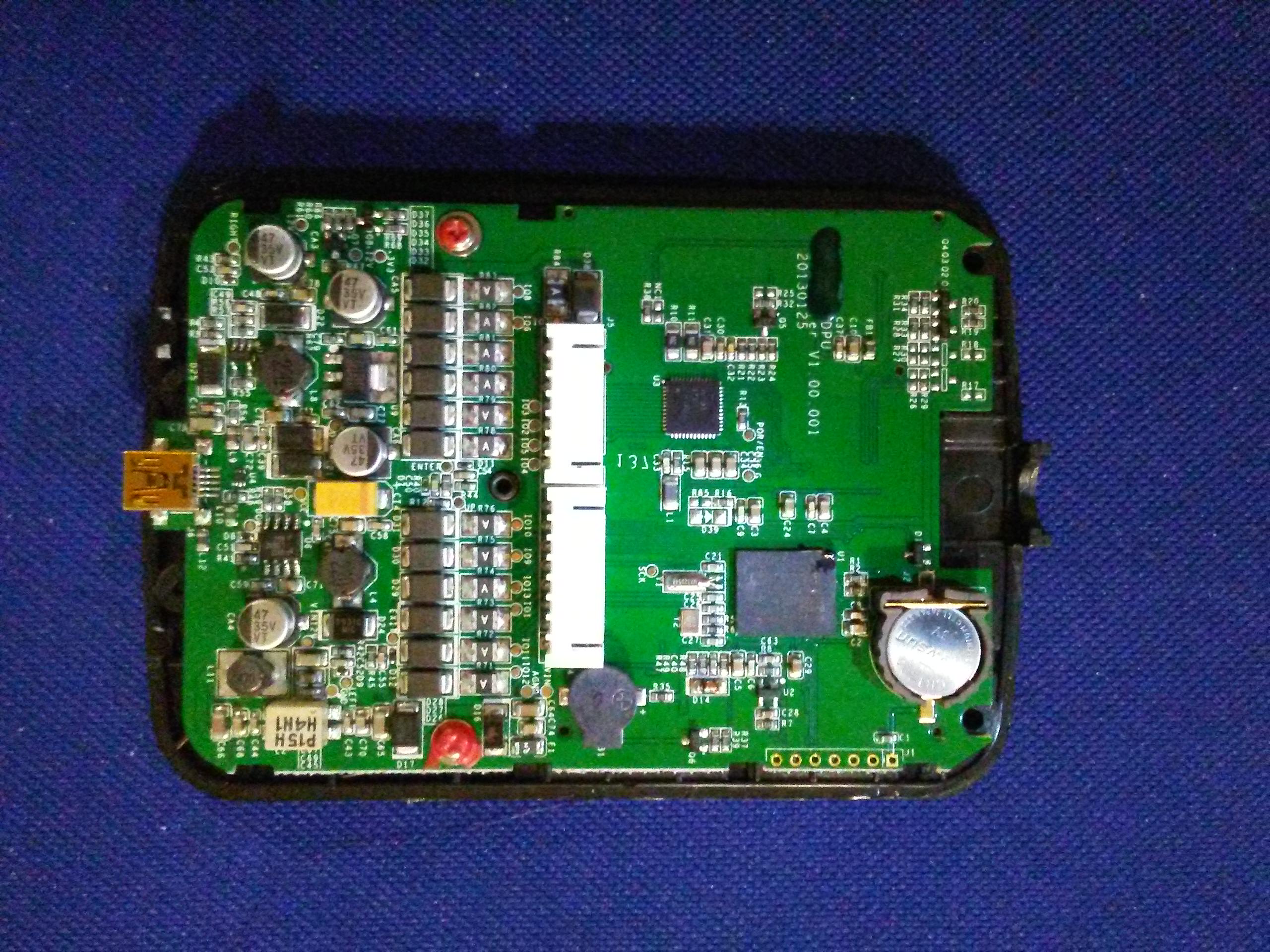
i don't have a VCI, but a "clone" from iCarsoft, the i909. It only seems to be able to read data list items, DTCs, and clear some DTCs. It has no capability to upload firmware updates that i know of.

It uses SHENZHEN LAUNCH TECH chips, a DPU 431 [U1] and a JV 700 [U3], mentioned in USPTO Patent Application 20170046884, Personal vehicle diagnosis system and method based on mobile intelligent terminal. Both are proprietary chips with little to no information available on the websticle. These chips are made by JVD Inc, which was founded by Jerry VanDierendonck and takes pride in keeping custom chip secrets.

"Jerry graduated from University of Cincinnati in 1966 with his undergraduate degree in Electrical Engineering. After graduation, he continued to work for his co-op company Avco Electronics before moving to Texas Instruments where he began work with the now famous team, Boone, Cochran, & VanDierendonck, the team that developed the world’s first microcontroller. He also became one of a few individuals worldwide that could create programmable chips for calculators at Texas Instruments. Jerry received 9 patents for his work at TI. Later Jerry was lured to Silicon Valley where he worked at Litronix, Fairchild Semiconductor, Monosil, and LSI Logic before founding JVD Inc in 1982 where he served as the company’s president until his retirement in 2010."

If i get my hands on a VCI it will be opened immediately.

b6HcOHP.jpg
 
coulomb said:
So I've gotten an RPG image to disassemble, and it's not what I had hoped for. This seems to be the firmware for the VCI, the dongle that sits between the PC and the vehicle...
Edit: it looks like all the VE*.RPG files are firmware for various models and revisions of the VCI.
It's finally dawned on me: these aren't the main firmware for the VCI module; these are special ReProGram images, hence the .RPG file extension. They are special images with just one purpose: to reprogram an ECU image. There are various sizes of .rpg files; these carry larger or smaller images as "payloads".

This explains why one of the first things it does is display the message "Reprogramming ECU", and at the end of main, it says "Press Enter to restart VCI", and branches to 0xA000 0000. Presumably, 0xA000 0000 is the address of the boot loader, and the RPG image gets overwritten by its usual image, which does all the other things *except* for ECU programming.

It seems that not all MUT3 images (I have them for years 2012, 2016, 2017, and 2018) have iMiev specific files. In fact, the 2018 distribution doesn't seem to have RPG or CFF files at all. So I'm concentrating on the 2012 distribution for now.

I still can't find any clues to the CFF file format; it's certainly nothing like the RPG file format. By ignoring the first part of one CFF file, I can get it to make sense, [ edit: was "except for a series of pairs of 32-bit instructions that make no sense". I had the wrong processor variant; these are dispose and prepare instructions. ]

The RPG file payloads may not be so encoded, but I haven't had time to analyse any as yet. In the 2012 distribution, there is a folder with 89 RPG files, and it has a subfolder called CFF with 89 .cff files. So I thought that with one exception, surely the CFF images would match with the payloads of the RPG images. And perhaps (this seems like wishful thinking now that I type this), the RPG payloads might not be mangled as the CFF files appear to be.

But I can't seem to match them up. The four iMiev related .cff files all start with 9499; this seems to be a model code for the iMiev, and the string "miev" appears in all four of them (in paths to files in the header at the start of the .cff files). There are various version numbers embedded in the .rpg files, but so far I can't line them up.

I actually have five .cff files (one sent to me privately, the other four from the 2012 distribution). Three of these seem to be for the BMU, one for CMUs, and one (the largest) for the VCU. Nothing for the charger. However, as part of the image upload process, blocks of code ending in many FFs and with binary-round sizes (like 0xA60, or 0x1000) are sent. It's possible that one of these images is for the charger, and others for other small ECUs about the place. 0x1000 (4 KiB) is still pretty small for a charger; for comarison, the Elcon/TC chargers have 8 KiB.

It feels like I'm close, but that could be the Dunning-Kruger effect :)

The BMU image is for a Mitsubishi MH8106F, which I can't find any data on. Maybe I'm just poor at searching, but It seems to me that this is supposed to be some big IP secret, at least in comparison to other architectures where the manufacturer wants you to be familiar with the features of their product. But I'm amused by the number of companies that seem to be offering "tuned" versions of engine ECUs. You have to use these with special tuning tools, and the drop-down list of these is about 20 different units. So some people out there know about these things, but since there seems to be a cottage industry in reprogramming these things, they don't release the information. Frustrating.

[ Edit: Deleted "Some RPG files seem to carry two payloads." I had some indices calculated wrongly. ]
[ Edit: Removed paragraph about pair of instructions that made no sense. ]
 
datom said:
Yes, I'd come across that discussion in my travels. I think at the time I was a bit dismissive, since it seemed to be very specific to a particular model of car, and didn't seem to publish the CFF "decryption" script (only the results of one application of it). Perhaps I should comb through it for more detail.

It seems that cff files are encrypted.
Actually, I'm getting some frustratingly near-reasonable results just chopping off the first part of the .CFF file, the mostly-text part, that ends in a null. So maybe some are encrypted, and some aren't. Or maybe it's encrypted in such a way as to appear reasonable, yet it's not, just to waste the time of people like me :x

There's a lot of interesting stuff to be found there. I didn't know for example about the Pass-Thru CAN Software
that can be used instead of MUT III for certain tasks
That surprises me. The .rpg images are really quite complex. It seems unlikely that whatever the VCI is doing during ECU reprogramming can be readily "bypassed".

(does it work for iMievs?)
An excellent question. Maybe I'll eventually be able to answer that.

[ Edit: truncating -> chopping off ]
 
36_19_1.gif


Sigh. There is a .csv (basically, ascii readable) file in the RPGDATA folder that I somehow managed to ignore all this time. It tells me a little story about what all the .RPG files are for. In short, I've been largely wasting my time looking at the RPG files, at least the ones I have so far. [ Edit: and at least for the present goal of iMiev firmware. ] [ Edit 2: I suspect now that .RPG files potentially carry several firmware updates; if so, all would be related to a single issue / TSB (technical service bulletin). ]

I've still found no relationship whatsoever between .RPG and .CFF files, though I still suspect that a given .RPG "carries" inside it a .CFF, along with a very complex program to upload it via the VCI.

In case it's of interest to anyone, here is the data on what's in the .RPG files that I have from the 2012 distribution.

Code:
VE03071.rpg  Carisma - Countermeasure for smoke & engine hesitation when high speed
VE03072.rpg  Ditto
VE03073.rpg  Ditto
VE03074.rpg  Ditto
VE03076.rpg  Galant - Countermeasure for smoke/fuel consumption display & magnet
VE03077.rpg  Ditto
VE03078.rpg  Space wagon, as above
VE03079.rpg  Ditto
VE0307A.rpg  Ditto
VE0307B.rpg  Ditto
VE0307C.rpg  Space wagon - Countermeasure for output decline/smoke/fuel consumption display & magnet
VE0307D.rpg  Ditto
VE0307E.rpg  Space runner / wagon, as above
VE0307F.rpg  Ditto
VE0307G.rpg  Galant as above
VE0307H.rpg  Ditto
VE0307I.rpg  Space wagon as above
VE0307J.rpg  Ditto
VE0307K.rpg  Space wagon - Countermeasure for smoke/fuel consumption display & magnet
VE0307L.rpg  Ditto
VE0307M.rpg  Ditto
VE0307N.rpg  Ditto
VE0307O.rpg  Space runner, as above
VE0307P.rpg  Ditto
VE0307U.rpg  Colt/Lancer - Countermeasure for cold hesitation
VE03081.rpg  Ditto
VE03082.rpg  Ditto
VE03083.rpg  Ditto
VE03085.rpg  Pajero - Countermeasure for miss MIL light ON/engine hesitation when cold...
VE03086.rpg  Pajero - Addition ETV position gap detection
VE0308A.rpg  PAJERO/MONTERO - Countermeasure for the high boost
VE0308B.rpg  Ditto
VE0308C.rpg  Ditto
VE0308J.rpg  Carisma - Correct fuel consumption display
VE0308K.rpg  Ditto
VE0308L.rpg  Ditto
VE0308M.rpg  Ditto
VE0308N.rpg  Ditto
VE0308O.rpg  Space Star - Countermeasure for error MIL light ON
VE0308P.rpg  Ditto
VE0308Q.rpg  Ditto
VE0308R.rpg  Space Star - Correct fuel consumption display
VE0308S.rpg  Ditto
VE0308T.rpg  Ditto
VE0308U.rpg  Ditto
VE03091.rpg  Ditto
VE03092.rpg  Carisma - as above
VE03093.rpg  Ditto
VE03094.rpg  Space Star - Correct fuel consumption display
VE03095.rpg  Ditto
VE0309C.rpg  L200 - Countermeasure over heat
VE03101.rpg  Space Star - Shock countermeasure of during slow driving with first gear
VE04061.rpg  PAJERO/MONTERO - Countermeasure of hydraulic flywheel
VE04062.rpg  Ditto
VE04063.rpg  Ditto
VE04064.rpg  Ditto
VE04065.rpg  Ditto
VE04066.rpg  Ditto
VE04067.rpg  Ditto
VE04069.rpg  Ditto
VE0406E.rpg  Ditto
VE04091.rpg  Carisma - Countermeasure for engine hard start at extremely cold condition
VE04092.rpg  Ditto
VE04093.rpg  Ditto
VE04094.rpg  Ditto
VE04095.rpg  Ditto
VE04096.rpg  Ditto
VE05021.rpg  Space Star - Countermeasure for engine hunting around 1500RPM on slight down hill
VE05022.rpg  Ditto
VE05051.rpg  L200 - Countermeasure for high idling
VE05052.rpg  Ditto
VE05053.rpg  Ditto
VE05054.rpg  Ditto
VE05055.rpg  Pajero Sport - Countermeasure for high idling
VE06111.rpg  Lancer - Change data related to engine startability at low temperature(for Russian fuel)
VE06112.rpg  Ditto
VE06113.rpg  Ditto
VE06114.rpg  Ditto
VE06115.rpg  Lancer - Delete intermittent control of A/C. Change IG timing for knocking suppression...
VE07041.rpg  Lancer Evolution - Change F/C to prevent over rpm limit resulting in catalyst damage
VE08111.rpg  Pajero - Judgement value of the overboost was changed. Judgement time of the overboost was changed
VE08112.rpg  Ditto
VE08113.rpg  Ditto
VE08114.rpg  Ditto
VE08115.rpg  Ditto
VE09021.rpg  Pajero/Montero - Optimization of fuel control on deceleration. Changed ISC control on engine starting
VE09022.rpg  Ditto
 
Another reverse engineering nerd specific post; feel free to skip if this isn't you.

It's taken me a while to learn the tricks of the CMU's compiler. It loves its register branch instructions, so some functions use the link pointer for the return address (as you'd expect), and others use random other registers. Why not, I suppose, when you have 32 to play with. It makes it very hard to visualise the control flow, and of course Ida Pro's guesses as to where the functions start and end are sometimes wrong, and tedious to fix. Most functions start with a branch to the end of the function, where there is a prepare instruction (a procedure prologue), then another branch back to the real start of the function (just after that first branch). I'm sure that there must be a really good reason to do that, but it eludes me.

In order to call functions from an array, which happens quite often, there is a problem: there is no call instruction that takes a register as the destination; it's always a constant. So they use this complex sequence; in this example, the address of the function to be called is in r16:
Code:
movhi   1, r5, r1
movea   (loc_96DC & 0xFFFF), r1, lp
jmp     [r16]
loc_96DC:
So the movhi instruction moves 1 to the top half of r1, and adds the contents of r5. What's in r5? It was set waay back before the start of main to be zero. There's a perfectly good always-zero register (r0), but they always use r5. I can only imagine it's good for debugging or some such thing. The movea moves the lower half of the destination (0x96DC), and adds r1, and the result goes to the link pointer. So that's the return address. But wait: there is no one in the upper half of the address! Because the destination (0x96DC) has the sign bit (bit 15) set, the offset is sign extended to be a negative number. Negative offsets are wonderful to this compiler :) But this negative number added to the 0x10000 already in r1 results in the correct 0x96DC. I finally twigged to this when I got to some code where the destination really was above 0x10000 (64 KiB), and it actually made sense. In many cases, these weird sequences are the only way execution gets to the destination, so of course Ida Pro can't recognise that it's code, and it starts off as unexplored data. That causes a cascade of unexplored code that is called only by that code. At least there isn't much data interspersed between the code, so it's largely a matter of marking big blocks of data as actually code.

99% of references to RAM are via the global pointer register, gp. I've finally figured out how to use enough of Ida Pro's user-defined offset to get what I need, but RAM references end up looking like this:

ld.b (byte_3FFD88C - 0x4005000)[gp], r11

That's just loading the byte at 3FFD88C to r11. The global pointer always contains the strange value 0x4005000, which is 20 KiB past the end of RAM, so all the references to RAM are with negative offsets. But it can't reach all the way to the start of RAM (0x3FF8000), so it seems to me that the first 0x3000 (12 KiB) of RAM are special or different.
There is also some special hardware or external RAM mapped to 0x3FEC000-0x3FFFFFF, which are referenced with negative offsets from r1. Because... negative offsets are beautiful!

The code is also very heavy with its use of arrays. There are arrays in RAM and also plenty in flash memory as well. There are arrays of pointers to functions, pointers to RAM (which point to other parts of RAM, or act as indices into other arrays), or of course to other structures in flash or RAM. There are many "arrays" in flash with one entry, always accessed with index 0, so the value is always a constant. :roll:

While I'm at it, here are the two most useful manuals for CMU work:
R01US0037EJ0100: V850E2S User’s Manual: Architecture (for the instruction set)
U18743EE1V2UM00: User’s Manual V850ES/Fx3-L 32-bit Single-Chip Microcontroller
[ Edit December 2020: was R01UH0129ED0701: V850E/Dx3 - DJ3/DL3 32-bit Single-Chip Microcontroller (for the many special function registers). This seems to be the wrong manual. ]
Hopefully useful soon: Linear Technology Multicell Battery Stack Monitor manual; the command codes for the LTC6802 chip start about half way through the manual.
[ Edit July 2023: The URLs for most if not all the manuals are dead. Google Drive save of the hardware registers manual; CMU processor's instruction set manual. ]

With these breakthroughs, I hope to finally get to the meat of the code. It's been frustrating to date, seeing lots of code, but none of it does much so far.

That's for the CMU (Cell Management Units). It would be better to reverse engineer the BMU code, or the charger, but I don't have a .CFF file for the charger, and I've made no headway at all with the code for the BMU, other than hopefully finding what looks to be the correct processor series (M32r series). My suspicion is that most CFF files are encrypted, but the CMU code may have fallen to a junior engineer, or the engineer simply forgot, or thought it wasn't worth the effort to encrypt. With that in mind, I've had a few quick passes over the MUT PC software, but I haven't hit on a reference to CFF files as yet.

Edit: I meant to add a paragraph about the PC-relative addressing. For a long time, I had no idea where the start of the code is; it turns out to be about 0x55AE, but perhaps the real start is 0x6000). All branch instructions are PC-relative, so they're no help. Often you can find interrupt vectors, but I still haven't found one that ends in a reti (return from interrupt) instruction. Eventually, I found some absolute addressing code, but it wasn't special enough to be able to find it in 384 KiB of flash memory. Eventually, I found one that had a particular "signature" (like an array of structures containing a pointer to RAM that was always followed by a byte), and was able to match it to such a pattern in flash memory.

Oh, one last whinge. Ida Pro (which goes back to the glory days of 16-bit 8086s) talks about bytes (8-bit), words (16-bit) and longs (32-bit). Modern 32-bit machines such as this one talk about bytes (8-bit), half-words (16-bit), and words (32-bit). The number of times I've seen a load.w instruction and thought that it refers to a 16-bit thing like word_876C is... too many :eek:

[ Edit: added sentence about flash arrays with one entry. ]
[ Edit: Added link to LTC6802 manual. ]
 
Great work as usual, thanks for sharing. i know you have the knowledge, skills and abilities to solve complex codes such as this, and so encourage you to endeavor to persevere.

Makes you wonder who wrote the compiler with all the bizarre and complicated twiddling just to point to a jump address or a memory register.

And then to use different families of processors across various ECUs is a strange strategy. Seems that commonality would lower costs for development and testing, etc., but maybe it was done intentionally to avoid mistakes of loading the wrong code..?
 
More information on the 2012 distribution. This is the starting post:

https://mhhauto.com/Thread-MUT-III-2012

In the first post of that topic, there is a .rar file. It just contains a .torrent file, which allows you to download a CD-Rom's worth of install data (about 800 MiB). I note that there are passwords mentioned in later posts, but I've not had the opportunity to use them as yet.

There are two main folders: PRE11121-00 and CD3E11121-COPY MASTER. I think you're supposed to install the first one first, then the second folder is a sort of add-on (edit: in fact, an update). Both folders have their own InstallShield executables. When I try to install the former, I get a message box with "The M.U.T.-III system has started. Please suspend a M.U.T.-III system, reboot a personal computer, and start UPDATE."

"UPDATE" probably refers to the other folder, see below.

All the folders in PRE11121-00\INSTALL have encrypted cabinet files; they seem to have customised InstallShield individually for each folder. I see talk of PUBLIC_KEY, and I may have stumbled onto one of the private keys. It could take decades to sort all that out.

But I think that the interesting part for iMiEV users is in the second folder, CD3E11121-COPY MASTER. One subfolder, CAESARCOMPDB, seems to have encrypted cabinet files, and may contain information about the CFF files. So I might make an effort to install that one day. I get "M.U.T.-3 system has started. Please perform after ending M.U.T.-3 system" for the CD3E11121-COPY MASTER update. Maybe it's OK to have the 2018 MUT system, and still use the CD3E11121-COPY MASTER update files.

However, one folder of CD3E11121-COPY MASTER doesn't seem to be part of an encrypted cabinet; it's MUT3\RPGDATA. It contains some 88 .RPG (ReProGram) files, and a similar number of .cff files in CD3E11121-COPY MASTER\RPGDATA\CFF. In my earlier head-slap post, I mentioned how the .RPG files seem to be all for other vehicles. Only four files, all starting with 9499 (this seems to be a product code for iMiEVs), seem to be iMiEV related. I have one other iMiEV file from another source, and it appears to be another version of two of these four. Of these five iMiEV related files, only one, which appears to be the firmware for the CMUs, seems to be unencrypted. Given the paranoia associated with all the other MUT-III files, this seems to be a miracle. Unfortunately, it's looking very much like the CMU processors don't do all that much, despite their quite complex firmware. All they seem to do is to send data to the LTC6802 battery stack monitor chips, copying the commands downstream, and sending the data upstream to the BMU. I don't see any of the commands, since these would come to the first CMU from the BMU. There doesn't seem to be any interpretation of the results; that seems to all happen in the BMU.

So at present, I'm stuck. I need to figure out how to decrypt the four encrypted .CFF files (three are for the BMU, one for the EVECU). It also appears that out of all this data, no file contains the charrger firmware, encrypted or otherwise. Hopefully, I'll get some inspiration soon.

[ Edit: added sentence about passwords mentioned in later posts from the first link. ]
 
CAN bus messages on the BMU to CMU private bus

I'll attempt to give these messages in the format of Decyphering iMiEV and iON CAR-CAN message data . Since these messages are only on the private BMU to CMU CAN bus, and seem to be modified when they reach the BMU and the main vehicle CAN bus, this will only be of interest to those wanting to use the CMUs that come with the iMiEV battery, without using the iMiEV BMU. Since the CMUs are buried inside the battery, it makes sense to make use of them.

I have not used these, or captured data from a real iMiEV; this is all from reverse engineering the CMU firmware. I'm finally making some progress in that direction.

Cell and temperature sensors will be numbered from one as the lowest number. It may be of interest to some to compare these with the 6D1-4 / 6E1-4 messages documented over 6 years ago by garygid in this post.

From CMUs to BMU

6n1, where n is the CMU ID, 1-C, for the 12 CMUs:
6n1:D1 = 0x20 (if boolCan1) + CMU ID. So either 21 to 2C or 01 to 0C.
6n1:D2 = bypass bits. Each bit will be set if the cell was actually bypassing at least sample.
6n1:D3, D4: Temperatures 1 and 2. I believe that these are in whole °C with a -40°C offset. So temperature = value - 40. Limits 20 - 130 representing -20°C to +95°C. I can't be certain about the offset (-40).
6n1:D5 & D6 as ((D5 * 256) + D6) / 200 + 2.1 = cell voltage 1
6n1:D7 & D8 as ((D7 * 256) + D8) / 200 + 2.1 = cell voltage 2

6n2, where n is the CMU ID, 1-C, for the 12 CMUs:
6n2:D1 = 0x20 + CMU ID. So 21 to 2C.
6n2:D2, D3: Temperatures 3 and possibly 4. Same encoding as above. D3 will be zero if n=6 or n=12 (4-cell CMUs).
6n2:D4 = 0.
6n2:D5 & D6 as ((D5 * 256) + D6) / 200 + 2.1 = cell voltage 3
6n2:D7 & D8 as ((D7 * 256) + D8) / 200 + 2.1 = cell voltage 4

6n3, where n is the CMU ID, 1-C, for the 12 CMUs:
6n3:D1 = CMU ID. So 01 to 0C.
6n3:D2, D3: Temperatures 5 and 6. Same encoding as above.
6n3:D4 = 0.
6n3:D5 & D6 as ((D5 * 256) + D6) / 200 + 2.1 = cell voltage 5
6n3:D7 & D8 as ((D7 * 256) + D8) / 200 + 2.1 = cell voltage 6
I believe that CAN IDs 663 and 6C3 (for CMUs 6 and 12) will not appear [ Edit Sep 2023: verified. ]

6n4, where n is the CMU ID, 1-C, for the 12 CMUs:
6n4:D1 = CMU ID. So 01 to 0C.
6n4:D2, D3, D4: All 0.
6n4:D5 & D6 as ((D5 * 256) + D6) / 200 + 2.1 = cell voltage 7
6n4:D7 & D8 as ((D7 * 256) + D8) / 200 + 2.1 = cell voltage 8
I believe that CAN IDs 664 and 6C4 (for CMUs 6 and 12) will not appear [ Edit Sep 2023: verified. ]

6nF, where n is the CMU ID, 1-C, for the 12 CMUs:
To be completed.

From BMU to CMUs
3C3:D1&D2 as ((D1 * 256) + D2) / 200 + 2.1 = bypass voltage (bypass if cell voltage exceeds this value, and bypassing is enabled)
3C3:D3 =0 to disable all bypass bits; =1 or -3 to bypass when cell voltage exceeds the threshold voltage; =2 to set all bypass bits.
With value 1 but not 3, if the threshold voltage (NOT cell voltage) is < 2.5 V or > 4.3 V, then turn bypass bit off.
With all values of this byte, if the cell voltage is > 4.3 V, the bypass bit is turned off.
3C3:D4[0-2]: other flags, use not determined as yet. But bit 2 may enable auto-renumbering.

6F0: Similar to 6Fn below, but manipulates many flags, possibly including the stopping and restarting of CMU data to the BMU. At one point, calls the same code that handles 6Fn messages.
6Fn, where n is the CMU id (1-C): Still unknown, but seems to result in some data sent over 3-wire SPI. These connect to the EEPROM, the S93C76A part.
D1[7-4] is an opcode, 0-3.
Opcode 0 has a 4-bit data length in the lower nibble of D1. I'm guessing the data, if <= 7 bytes, is in the rest of the message (D2-D8).
Opcode 1 has 24-bit length, upper 4 bits in lower nibble of D1, rest of length in D2.

There appears to be another CAN packet, or possibly serial packet, that mimics the above (i.e. it provides alternative bypass threshold and enable bit). I have yet to determine where this comes from (handler at 0x0E3C0).

To be completed.

[ Edited December 2020: Added mention of 6F0 and 6Fn. ]
[ Sep 2023: Verified messages 633, 634, 6C3 and 6C4 do not appear. ]
 
Posted wiring harness details in my CMU circuits thread.

The HV digital isolator chip, AD UM1402W, passed 4 signals across an ~4mm isolation gap in the copper, which i will refer to as the HV (pack side) and LV (module side).

Two signals across the gap into the LV side: the CMU pin 3 serial comm into micro pin 37; and the RxD output (pin13) of the TLE6250G CAN transceiver chip to pin 16 of micro.

Two signals from the LV side: micro pin 18 to the TxD pin 1 of CAN Tran; and micro pin 36 out to CMU connector pin 7

There are 4 electrolytic caps on the board that share same ground plane on their respective sides:

2 on the HV side
100uF 35V holds 12VDC
47uF 16V holds regulated 5VDC

and 2 on the LV side
100uF 35V holds the module voltage (depending upon 4- or 8-cell module)
47uF 16V hold regulated 5VDC

Schematic-type circuit drawings can be found there also.
 
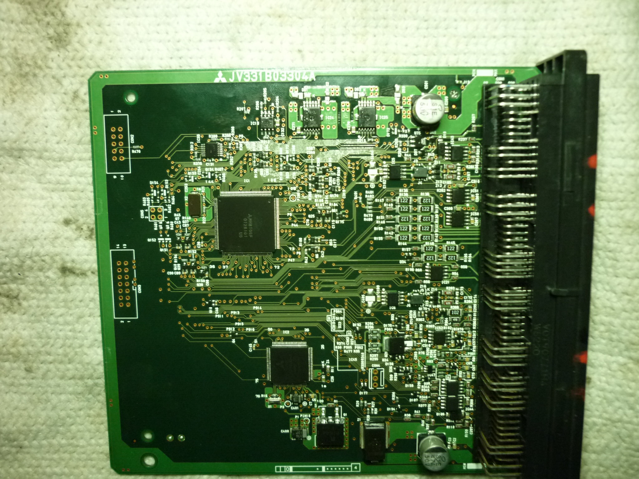
I'm going to post a photo of the EV-ECU board here, just because I confused a BMU with this one.

It's easy to tell them apart (when your brain is working, as mine was not): the EV-ECU has 4 3-level connectors; the BMU has 2 2-level connectors. The EV-ECU seems to be a fair bit bigger, maybe almost twice the linear dimensions (almost 4 times the area). Duh.

They both have the same main processor: MH8106F.

BxrFwXv.jpg
 
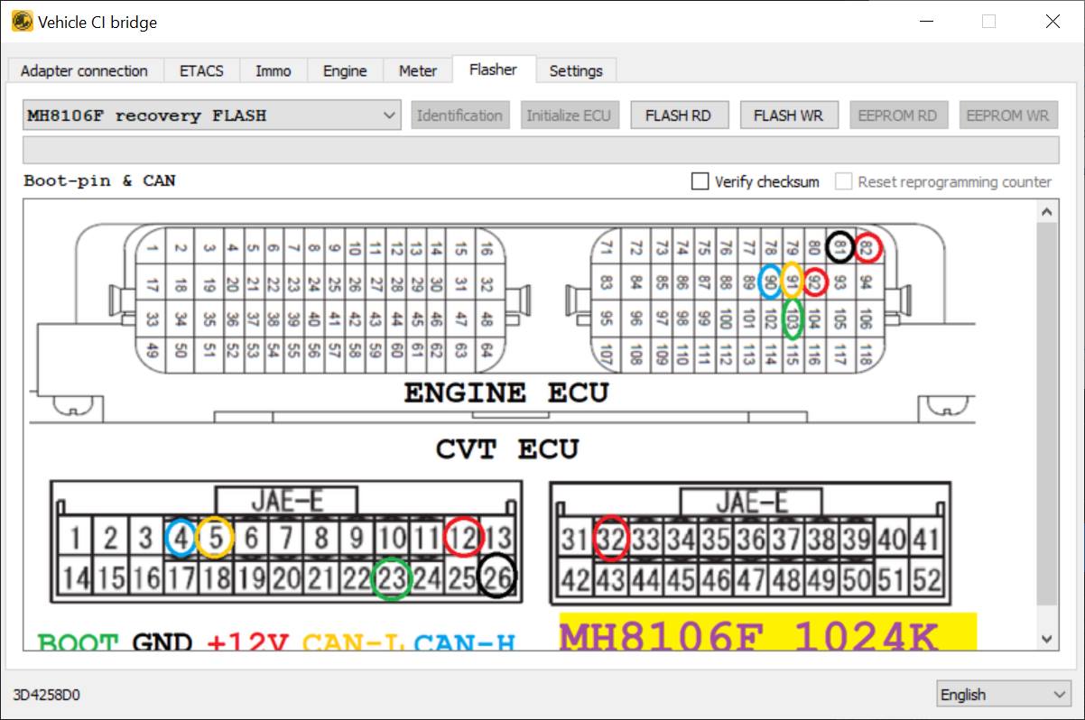
It seems that it may be possible to read the firmware of a BMU, using Russian software that costs US$60 and a little hardware. I'm very hazy on the details, but it seems that we need to find the BOOT signal. It's not marked on any schematic that I'm aware of. My suspicion is that it will connect to a particular pin of the MH8106F microcontroller, probably via some buffering or at least protection.

From Facebook page MMCodingWriter - tool for manage ECU coding on Mitsubishi vehicles:

"World first. Recovery mode for MH8115F & MH8106F via CAN-bus. Later also will be added repair for MH8601 (Eclipse Cross) and old k-line. (Recovering and reading ECU from any state - bricked, locked, etc)
https://forum.kolyandex.su/viewtopic.php?f=14&t=281"

136955653_1794093917411190_1685773991625567269_o.jpg

tFScdhU.jpg


The pin diagram will be from some common Mitsubishi engine and transmission ECU. It looks like we'll need to find the BOOT pin.

On Facebook, I asked:

"I see the above is intended for ECUs for engines and transmissions. Is there any chance that the same techniques can be used to extract BMU (Battery Management Unit) firmware from Mitsubishi iMiEVs, and possibly Mitsubushi Outlander PHEVs? They use an MH8106F microcontroller.
Or is every CMU firmware access completely unique?
In your opinion, what are the chances that one of the known bootloaders from an engine or transmission would be used in the BMU? I'm guessing that this is critical to success in reading firmware."

The reply from the author:

"I think bootloaders are same and that method will work."

I'll have to try and get my hands on a BMU to try to read it, the VCI hardware, and this software. In the meantime, does anyone have any clues on how to find the BOOT pin? Do we have any data on the MH8106F processor? It seems they deliberately are keeping it obscure, presumably because they don't want people messing with engines and causing danger and/or pollution.

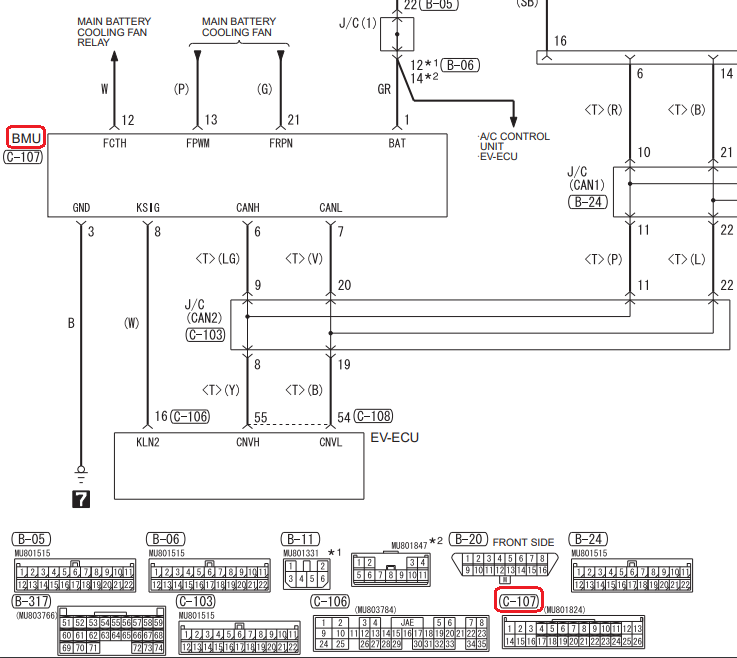
We know a few connections to the BMU from this schematic:

KHhdRgW.png


Anyone know what KSIG on the BMU is about? Could this be "K-line" communications, that ends up at the OBG-II port?
 
i wonder if there might be a Boot pin on the JTAG interface on the BMU board?

There seems to be 2 approaches to modification of the battery capacity for upgrading or replacing the pack with larger cells, either spoof it with a CAN bridge (man in the middle) or change/reprogram the value in the BMU.

Do you have any thoughts or opinions about those approaches and the likelihood of success?
 
kiev said:
i wonder if there might be a Boot pin on the JTAG interface on the BMU board?
Could be. But the BMU firmware seems to be encrypted; only the CMU firmware seems to be unencrypted.

There seems to be 2 approaches to modification of the battery capacity for upgrading or replacing the pack with larger cells, either spoof it with a CAN bridge (man in the middle) or change/reprogram the value in the BMU.

Do you have any thoughts or opinions about those approaches and the likelihood of success?

I had pretty much given up on making sense of the CMU code, and have not even been able to start on the BMU, because of the encryption.

But Kolyandex seems to have a way of getting to the firmware, and has "reversed" it:
https://myimiev.com/forum/viewtopic.php?p=44300#p44300

But he seems to be more of a "buy a solution from me" than a "share what I know" kind of person.

Given the difficulty of dealing with Russian companies in the present circumstances, it seems to me that the CAN bridge solution is far more practical at present.
 
Back
Top