How to remove main battery pack?

Mitsubishi i-MiEV Forum

Help Support Mitsubishi i-MiEV Forum:

This site may earn a commission from merchant affiliate links, including eBay, Amazon, and others.
Don said:
I'm guessing this fan is one of several differences between CHAdeMO equipped cars and all others?
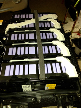
All i-MiEVs have the Traction Battery Fan for cooling (something not found in the Nissan Leaf). With the Quick Charge Option, the i-MiEV battery pack also draws cold air from the air conditioning unit.
From Mitsubishi Motors website:
"The custom-made battery pack on the ES trim of the i-MiEV features a fan-driven, forced-air induction system that automatically engages to protect the battery from overheating during charging. Drivers can upgrade to the Premium Package, which also gives drivers the ability to charge the i-MiEV using public quick chargers. Because quick-chargers can tend to heat batteries and reduce their efficiency in the long term, we've added an air-cooling system that draws cold air from the air conditioning unit to keep the battery nice and cool, even in hot climates."
 
Ben Nelson has posted a video where he removes and dissects this fan.
http://300mpg.org/2013/05/05/i-miev-battery-pack-air-cooling/
 
I pulled the battery pack out of my new I-MiEV over the weekend (cause I already mowed the grass). Put it back in tonight and everything works fine. I just wanted a look inside to see what was there and what was not. I jacked the car up and put four truck jackstands under it so I could get it high enough in the air---in my case 19" from the frame rails to the ground. I used a bubble level to set the pack level with the floor. I used a "Handylift" motorcycle platform lift which has a two foot by seven foot flat top on it (after removing the motorcycle wheel clamp). Before sliding the lift under the car, I removed the two front mount bolts, two power cables, A/C and heater power cables and finally the three control wire connectors. I then put a movers blanket on the top of the lift and postioned it under the pack. I then removed the 12 volt battery ground cable and the high voltage interlock plug. I also pushed the boot around the plug under the floor at the same time. The lift has a 1500 pound capacity and is air operated so I applied air pressure until it was firmly pushing on the bottom of the pack. I removed the two small brackets on the sides of the pack near the rear. I then removed the final eight support bolts and lowered the pack to the ground and rolled it out from under the front of the car. I then took the top cover off the pack. I am glad I watched Ben's videos (thanks) before I did it as there are a couple of sneaky bolts securing the high voltage interlock to the top (along with four spacers that you will find after the cover is off. Inside, as I suspected and if you read my replies in the battery temperature management thread, there is no cooling system for the pack. The pack is entirely sealed except for a small outlet on the top with a little foam filter in it. On the front of the top cover you can see outlines of where the cover would be cut for a cooling duct for both L.H and R.H drive vehicles. If you turn the cover over, you can see the area that the fan would mount to and the rubber plug the closes off where the fan wires would exit. The nutserts for mounting the fan are installed in the cover. There are no battery cooling tubes inside the pack. There are 10 sets of LEV50-8 modules and 2 sets of LEV50-4 modules. The modules are marked 50 ah, and 1440 and 720 watthours depending on size. Each battery has a balancer mounted on the top along with temperature sensors. six sensors on the -8's and four on the -4's. There is a ton of wiring in the compartment but most of it runs to connector blocks that parallel all the wires. There are three contactors in the center of the pack--battery +, battery -, and a charging contactor. There is also a ground fault unit present. The battery management unit is inside the car and I couldn't find any other electronics in the pack. There is a CAN bus loop between modules and the BMU that addresses each cell in the modules. CMU-06 and CMU-12 are the -4 modules. The internal construction is really nice---everything is a buss bar connection, no cables between the modules. You can sure see way these cars cost so much. Wrapping everything up and putting the pack back in was a snap. The blanket was the key to this as it allowed me to slide the pack on the top of the lift for the final lineup. If I could only get a place for my picutres to go, I would be glad to share.
 
siai47 said:
If I could only get a place for my pictures to go, I would be glad to share.
I use imgur.com for posting pictures. It's pretty easy to upload your pictures there.
When you post, the text for an image will look like this (the okAtCSj will be different):
http://i.imgur.com/okAtCsJ.jpg
Highlight the address and then click the Img button (or just leave the address and we can click on it and view the image).

Great information!
I would love to see the pictures.
 
Wait... What? You removed your battery pack "just because"? Me thinks I have joined a forum that actually out-geeks myself!
 
RobbW said:
Wait... What? You removed your battery pack "just because"? Me thinks I have joined a forum that actually out-geeks myself!

Sounds like fun! I think in the future we'll all be learning how to do this. It will be part of EV maintenance. Why go to the dealer and have them rip you off - when you can do this yourself. Buy all the batteries you need and replace them yourself. We'll also need to get access to the Controller as well to make any adjustments for new batteries.


siai47 - for the betterment of all i-MiEVkind, I would love to see these pictures. Do you think you'll be able to modify your battery pack to include cooling? A great DIY project for sure.
 
MLucas said:
Sounds like fun! I think in the future we'll all be learning how to do this. It will be part of EV maintenance. Why go to the dealer and have them rip you off - when you can do this yourself. Buy all the batteries you need and replace them yourself. We'll also need to get access to the Controller as well to make any adjustments for new batteries.
You make a solid point, good sir knight! Once our MiEVs are out of warranty and need battery replacement, this should definitely be much cheaper than having the dealership perform the exchange. Hopefully by that time, battery technology will have advanced to the point that they will be cheaper, hold way more capacity, and still be compatible with our MiEVs!
 
siai47, thank you for your excellent writeup and I'm looking forward to your photos. Interesting that Mitsu uses distributed cell balancers (commonly used for large-format cells), and thus monitored/controlled by what is probably a proprietary bus - making it more difficult to hack into. Glad to hear the cells are readily-identifiable. Just the beginnings - MLucas, I like that phrase: "for the betterment of all i-MiEVkind" :cool:
 
Thanks again, sia47, tis a service to all.
Regarding battery replacements, that's another reason I picked the i over the Leaf. Large prismatics have been more accessible to the EV conversion hobbyist and are easier to work with than other formats, and if necessary today, the i-pack could be rebuilt (albeit at lower capacity) with "off-the-shelf" cells from other makers. BUT, with over 27,000 of these packs on the road worldwide (2.3 million cells!), that's a market that should attract a vendor of replacements even if OEM cells are unobtaniuim in 7 years or so...
 
This is my first attempt of downloading some pictures.....Try this link

http://imgur.com/a/Dug92
 
OK--the link worked! Picture #1 is the motorcycle lift with the movers blanket positioned under the car. #2 is pulling the pack from under the car #3 is the pack on the raised lift--look carefully and you might be able to see marks indicating where the cooling ducts might go near the top front of the pack. You can also see the vent for the nonexistent fan on the top rear of the pack cover. #4 is a cover around the high voltage interlock that when removed covers four additonal bolts which were removed in picture #5. These are the bolts the Ben didn't remove when he took the top cover off which pulled the interlock recepticle apart. #6 shows the four spacers under the top cover that are loose once you pull the cover off. #7 is the front row of five LEV50-8 Modules---you can see the buss bar covers (white) connecting each Module. #8 is the rear row of five LEV50-8 Modules. #9 is the center of the pack--on the right bottom and top you can see part of the two LEV50-4 Modules. The area where all the connectors are is above the three high voltage contactors. #10 is a closeup of the connectors and on the right side is the edge of one of the Modules showing the connector for the battery balancer for that Module. Most of the connectors are actually junction blocks that connect the wires together. You will notice some of the connectors have all the same colored wires in them. #11 at the bottom is where the power feeds for the A/C and heater go out of the pack. One set of wires is going to a common ground. The other wires are going under the panel too the two 50 amp fuses located underneath. #12 shows the top of the 280 amp main fuse located where the QC cables would enter the pack (if I had the option) #13 is a picture of one of the LEV50-4 modules (hard to see) but they are marked 720 watt hours on the -4's and 1440 watthours on the -8's.

Well that's about it Hopefully in the weeks ahead I am going to start really messing with this car--permanently voiding any thought of a warranty. I will also post some pictures of my first hookup of my 12 KW charger (which works--just doesn't look too pretty yet)
 
For JoeS, I think the balancers will work automomously without being connected to the rest of the vehicle. There are only five wires in the connector on each module. I think (although not sure yet) that they are power, ground, CAN high, CAN low, and K-line. The CMU's (cell monitoring units) have their own CAN buss (with a K-line backup) to communicate with the BMU. The BMU seems to switch the CMU's on or off as needed--which is whenever the car is in the ready position. I will try to varify if supply 12 VDC to the CMU is all that is needed to have it actually regulate--you just won't be able to see the data. It might need a CAN signal from the BMU to actually start regulating. Looking at the powerline load charts some members have posted it looks like regulation isn't happening until the battery reaches a point of being nearly fully charged. I am not sure if these are I-MiEV only CMU's or something adapted from the Yuasa LIM commercial battery series. It appears that the LIM battery modules have the regulators mounted remotely from the cell in the front of the enclosure---unlike the LEV50's which have the PC board physically attached to the cells. For the LIM series, Yuasa provides software for tracking and recording the cell voltages, temperatures and power output.
 
So much effort... I want to see the photographs on high resolution, and I can only see them in a small image, like this :(
XrY5Q1H.jpg


Sorry, but would it be possible to re-upload in higher resolution?

Thanks in advance,
 
I don't know if I can. I used a hosting service suggested by a member here. This was my first attempt at doing this however the service resizes the photographs to a lower resolution. If anybody has any suggestions about a better service (for high resolution) post it here and I will try it.
 
Thanks siai47 for posting the pictures. This is very insightful. When you start digging around in the battery pack, would it be possible to get the physical dimensions of the cells? I'd like to compare them with what is commerically available today. Anyway, can't wait to see what you'll be modifying. I think what you are doing is going to really benefit a lot of people and may even spill over into the Leaf community.

I've been working with my MiEVCAN device and monitoring the temperature. I'm finding that it's usually a few degrees lower than the outside temps. Yesterday, it was 28c/82F outside and the battery pack was reporting back at 25c/77F. This brings up another question, I'm wondering if it would be worth it to insulate the battery pack by placing a foam board across the bottom of the car and up the sides. Or is the outside ambient temperature getting through the floor boards and into the top of the pack. I'm also wondering if this would help keep the heat in the pack during the winter as well. Any thoughts on this?
 
siai47, have a look at the lower voltages. I am told the i-MiEV does bottom balancing when below two bars and the gauge blinking. There is a war of religions raging between bottom balancers and top balancers with only the batteries of the bottom balancers surviving.

It has has been shown repeatedly, bottom balanced cells do survive deep discharge. Top balanced batteries reverse charge about half their cells killing them. The death of the first cell may occur with a battery that seems to have still a lot of energy because with 88 cells you dont miss a single flat cell. The car still runs.

Cheers
Peter and Karin
 
MLucas said:
I'm wondering if it would be worth it to insulate the battery pack by placing a foam board across the bottom of the car and up the sides. Or is the outside ambient temperature getting through the floor boards and into the top of the pack. I'm also wondering if this would help keep the heat in the pack during the winter as well. Any thoughts on this?
While insulation slows the transfer of thermal energy, unless you're heating or cooling the insulated space, it will eventually reach ambient temperature. If it takes the insulated pack 30 minutes to reach ambient instead of only 20, I just don't see what that gains you

I think it makes some sense to insulate the heater, since slowing the thermal transfer there results in an energy savings, since you're burning electricity to create the heat, so any heat you save results in an energy savings. Not so for the battery pack

Don
 
Don said:
MLucas said:
I'm wondering if it would be worth it to insulate the battery pack by placing a foam board across the bottom of the car and up the sides. Or is the outside ambient temperature getting through the floor boards and into the top of the pack. I'm also wondering if this would help keep the heat in the pack during the winter as well. Any thoughts on this?
While insulation slows the transfer of thermal energy, unless you're heating or cooling the insulated space, it will eventually reach ambient temperature. If it takes the insulated pack 30 minutes to reach ambient instead of only 20, I just don't see what that gains you

I think it makes some sense to insulate the heater, since slowing the thermal transfer there results in an energy savings, since you're burning electricity to create the heat, so any heat you save results in an energy savings. Not so for the battery pack

Don

Don - What if the charging process does create some heat, would it not make sense to insulate the battery pack to keep that heat in after taking the car off the plug? Or in the case we can manually manipulate the air flow door the way siai47 has and on cold mornings preheat the car and flip the door open to poor warm air into the battery pack.

siai47 - now that you have a way to upload pictures, can you take a photo of how you manipulate the battery air flow door?

Just thinking out loud - appreciate the feedback.
 
For member MLucas, the LEV50 cells are 113.5 mm high, 43.8 mm wide and 177 mm long. They weigh 1.7 KG each. They are also a 3.7 nominal volt cell.
 
We're getting a little off topic here but for member peterdambier I'll try to guess the answer to the question about battery balancing. It appears from what I can get out of the I-MiEV technical information manual, the batteries are top balanced during the final segment of the charge cycle. The battery management unit also will shut down the vehicle if any of the cells drop below a specfic voltage. If you had a cell that is not balancing or has limited storage potential, that one cell would affect the range of the entire vehicle. I think the I-MiEV is fairly conservative on low battery voltage. My I-MiEv showed the turtle when the pack dropped to 316 volts which is 3.6 volts per cell. The safe discharge level of the LEV50 cell is 2.75 volts. It sounds like a pack that is only charged to 4 volts per cell and warns of low battery at 3.6 volts per cell is giving up a lot of useful energy. That is not really the case if look at the cell capacity curves, there isn't really much energy left in the cell between 3.6 and 2.75 volts as the curve really takes a drop to almost straight down near the end. We are losing the most energy (about 8%) by not going up the full 4.1 volt rating of the cell---however, we are gaining cycle and calendar life by not going there.
 
Back
Top