I fixed something that was working - Now it is not working. OBC blew up resistor

Mitsubishi i-MiEV Forum

Help Support Mitsubishi i-MiEV Forum:

This site may earn a commission from merchant affiliate links, including eBay, Amazon, and others.

mwahlgreen

Active member
Joined
Jun 29, 2020
Messages
27
Location
Køge/CPH Denmark
Hey great internet Oracle

I beg for a fast reply (kiev?). I need to my car fixed in a jiffy :D

Car can quick charge, but not slow charge (type 1)
I loss two hours for charging everyday to charging in quick charge, however I can manage to go to work every day.

I changed the MCU fuse with original fuse from Mitsubishi Japan.
(link somewhere is this thread: http://myimiev.com/forum/viewtopic.php?t=4310, as I recall)
I changed the snubber caps on board with:
https://dk.farnell.com/vishay/564r60gad10/cap-1000pf-6-kv-20-z5u/dp/2860032

Q: What do I buy to replace parts: Resistors and relays in dog house?
Q: Did I buy and install the wrong snubber caps?

After I touched one resistor:
ACtC-3dMmzevSkxG089C_EqnAzgGX41xj9rGPovX0GMwIvo2futU9z3bCA_Abfc74xRwdLnNOCnCA2nLL2BWI6L-mvf8Yf10Ivt7IXXhr3yJPtuDa74K8G68Mx4v9HihmxXNk5LPiq7sZLuSXxNrajww45Ozhw=s938-no


Before I touched one resistor
ACtC-3eAWQsL-bQT7nJ2UsiOaygtPdP11aTvRE-1RV1Xa6XzHffCFoYD01jM2BQiieoZE7ZHX7mLL_8NbOebpiF1KQXGglVfHSO0dQlpdCLm494D_MZUWZDqzVsA780zGhixei3yZDTE5LO9pRtCO8VP7RiTPg=s938-no


Resistors after my upgrade, before I tested if the car could charge, look for them in the picture at the bottom:
ACtC-3fxos8CvONdETc0Go83W4x99LZ1GfWAU6Ck7mzOf8OCZ9cNQXuyIe9qvorKZdUpXL5oFwpbhWPvrCto6N3_aO-2WLowa2nfPRDNhHQwlUQAgyhcH2LPFJN4NeinwGoyFmcSGJCSfuOuTzG9sDkJvrzQSQ=s938-no


I found this, when I opened the DC/DC at before my "upgrade":
ACtC-3dBkzf8KHLXJmqAZubHD7lv7zCcOY74FbRMoV-WuewI00RYGFQFKNPLpA57KWzOHkJwh4u6MaPSE-S2qMhx2oAco5rw6_-Xs7lykp3n9ZzEy44TQtifyS4XWZg8Q9h2yDGNBdbnEdVkLbFtjwiLUJduPg=s938-no


The car was working before this.

I look forward to your help.

I have taken a lot of pictures and were planning to do a walkthrough.
 
The ceramic resistors and the black plastic relay are in the Input AC circuit; the snubber capacitors are on the Output DC circuit. Two separate unrelated circuits and separate failures.

In the before picture, one of the little capacitors on the snubber board can be seen to have been blown off the board. It may have still been working if the other caps were intact (2 in parallel, 2 in series).

The repair of the snubbers looks good and those are better caps than the original; the problem is that you touched the hot solder iron on the black plastic relay. That melted plastic may have damaged and locked up the relay internally, which then caused the ceramic resistors to fail. Or there could be some other fault with the control logic board such that it did not command the relay and the resistors had to carry the AC for too long a time period during the startup of charging.

Look at the pictures in LucasH's thread "Faulty onboard charrger", he had the same ceramic resistor failure.

i would recommend to replace the relay along with the ceramic resistors, and possibly the AC capacitor depending upon how much de-soldering you intend to do for the repair. Or take the board to an electrical repair shop to do the de-soldering. It is not a quick repair and not easy to do properly, but some folks have done patch jobs that work.

where are you located?
 
Hey

Located in Copenhagen, Denmark.

I will take a look at the thread you suggested (again).

LucasH however did not repair, he replaced the unit instead ;(

I am willing to do all the soldering myself. Electrical engineering as a profession.
However the soldering iron did mistakenly hit the relay housing in my previously attempt to repair the components in the dog house.
 
There may be other ways to do it, but i would recommend to desolder the waffle plate to allow access to the bottom layer of the board to replace the ceramic resistors, relay and capacitor. Hopefully you can get access to a vacuum desoldering station.
 
So my repair in coming along.

Question?
https://photos.app.goo.gl/c7vLPMKnowWLzhyT6

I am I correct that I should be able to measure connectivity between these eight connectors when put back together?

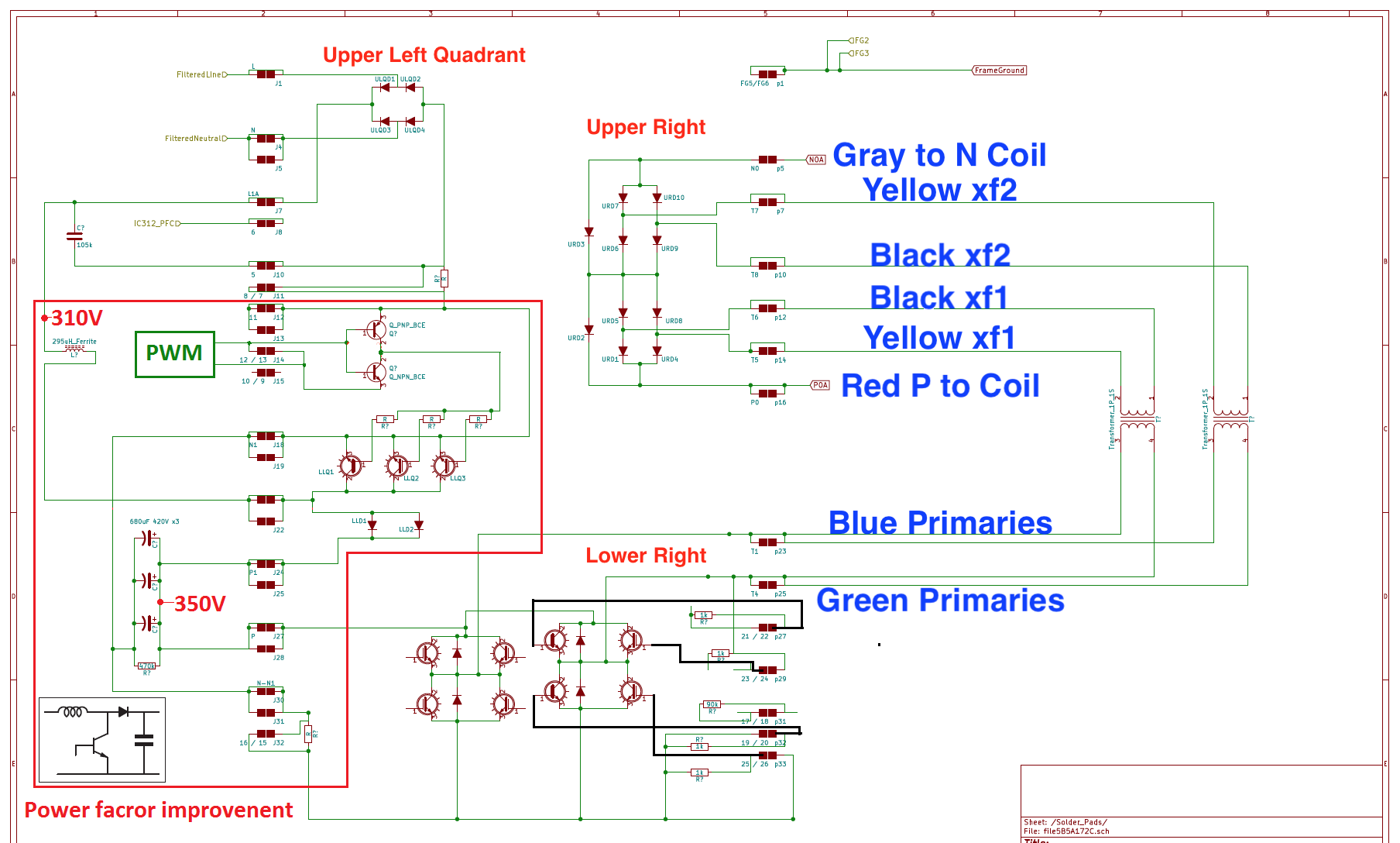
I found a diagram from what seem to be Kicad in the long "Troubleshooting... OBC..." thead, that suggest they are connected to a bridge rectifier and if I measured the "right way" there would be a connection.

I have had the Waffle plate removed and replaced everything. Had to do some repairs on the PCB due to heat and mechanical damage to the through hole vias.

I will try to reconnect everything tonight (18.00 CET) and power up again.

All my pictures, so fare can be found here:
https://photos.app.goo.gl/2zi3nzXxAQdDAg9YA
 
That looks like a good repair job. Great set of pictures showing all the vias and traces that needed some rework.

In post 2 of the big thread there is a link to this diagram showing the diode voltage drops in the waffle plate that can be measured to determine if there is any damage in the plate.
http://myimiev.com/forum/viewtopic.php?f=23&t=4079&start=440#p40562

The schematics are found in post 3 on the first page of the big Troubleshooting thread and this one shows the connections to those 8 pins. There are duplicates, such as the 4 marked "11" which go to the low side of the rectifier bridge upstream of the current sense resistor. "7 and 8" are across the current sense resistor, "5" consists of two pins that go to the low side of the rectifier on the downstream side of the resistor.

SBC5zA0.png
 
Thank you very much for your reply and all your help. I suck at being grateful and show it. :oops:

I will go an install the OBC back in the car in a couple of hours and we will see if I/we did it.

I went to a friend for help yesterday for the reassembly of the PCB, because I wanted to be 110% sure I did it right and I needed the confidence boost of a sparring partner.
 
i would recommend to check the diode drop voltages before powering it up--make sure there is no obvious issue with the waffle plate.
 
Back
Top