kiev
Well-known member
[Edit Feb 2024 With coulomb's help we are setting up an INDEX of this thread, hopefully this will assist folks to find frequently needed repair info,
The INDEX Link
[Edit Jan 2024 The forum software was updated and the page numbering is now different, links may not be anchored correctly (tbd)
Also there is now a 10,000 character limit, so this post had to be broken into parts.
part 2 here: #1,264
part 3 here: #1,263
/edit]
This thread will be used to document the technical information and any schematics or firmware available to help troubleshoot and repair the OBC/DCDC Converter
Post #2 has troubleshooting steps and an index of this thread
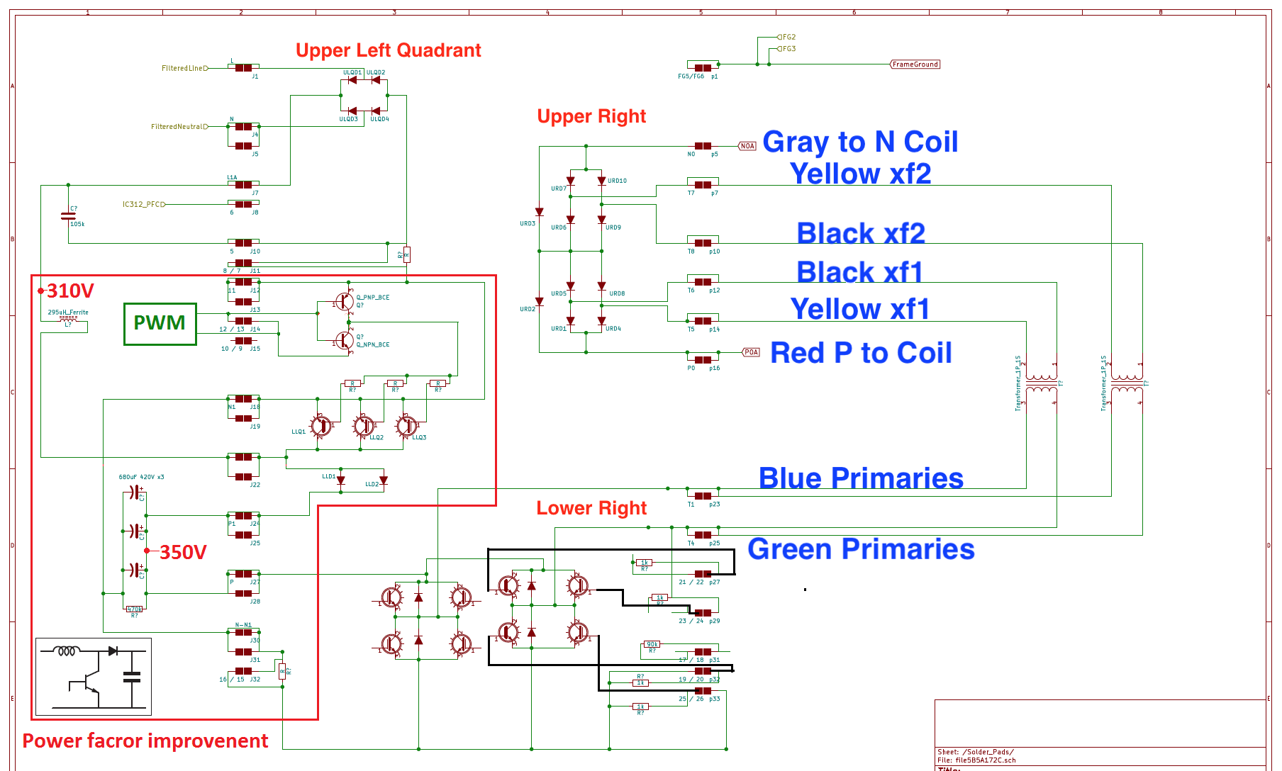
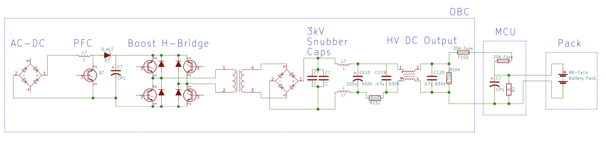
Post #3 will hold a collection of circuit schematics
[edit Sydney EV video link showing a snubber capacitor repair with OBC removal]
Sydney EV video of iMiev charger repair
[Original post June 2018] There seems to be many failures reported lately (last 6 months or so)
Links to user's failures [and successful REPAIRS] in reverse order, latest at top:
[2023 edit]
##. Coulomb (July 2023). 2010 earlier version OBC in Australia. Failed isolation amplifier board in the Output Sense and Filter section beginning on page 110. Successful Repair by Coulomb
##. Philsuth (Aug 2021 }. Investigation of a 2010 earlier version OBC in Australia. Complete disassembly with some great details and pictures beginning on page 76. PhilSuth
[2020 edit to add additional repair efforts]
##. LucasH (Nov 2020). Does not chargge, but DCDC is working. LucasH
##. ZetaFunction (July 2020). Sebastian's issue with the switching power supply on the bottom board, a new issue never seen before starts here: ZetaFunction on pages 54-59 still in progress.
##. DutchLincoln (June 2020). Great pictures of disassembly to repair damaged snubbers.
http://myimiev.com/forum/viewtopic.php?f=23&t=4079&start=500#p41150
[previous list]
21. 11/28/2018, Reports and more repairs by Skylogger in WA
20. PM message, 10/2018, from tdigsi; looking for substitutes to replace the 680 and 220uF capacitors?
[EDIT: REPAIRED, replaced snubber caps and MCU fuse, now it is charging; going to replace HV caps anyway due to age and high mileage, est. >~5000 Hrs on caps.]
19. PM message, 9/2018, from Quixotix in Seattle; dealer says charrger is dead; recommended to request DTCs and open cover to inspect for damage, blown fuse, etc.
18. ChristopheFR, 9/2018, 2011 C-Zero in France, EVSE charging appears to start then quits, DCDC appears to work ok, Aux battery changed in 2015
17. skylogger#2, 9/2018, 2010 in Western Australia, blown snubber caps and MCU fuse, AC relay and precharge Rs
[EDIT: REPAIRED--SUCCESS!, 9/2018 ]
16. footswitch, 9/2018, 2012 not charging in Portugal, EVSE charging appears to start, then just quits, DCDC appears to work ok, still running with OEM Aux battery.
15. charliejuliet, 8/2018, failed charrger in Michigan UP, replaced with aftermarket DC/DC and Chademo charrger.
14. redcane, 8/2018, 2010 not fully charging in Australia (east coast), OBC was replaced with a 2015 unit under recall in January 2017.
[EDIT: 1/8/2019,REPAIRED, replaced snubber caps and MCU fuse. Also replaced the pre-charge resistor, but that was not due to the OBC failure.]
13. skylogger, not charging in Western Australia, found blown surface mount capacitors.
[EDIT: SOLVED AND REPAIRED,8/12/2018, see picture of a twisted resistor causing open circuit on voltage monitoring]
12. beeline, 6/18, 2012 not charging, dealer estimates $4800+tax
11. mikedufty, 3/18, 2010 Australian model not charging fully in WA, charrger was replaced under recall. Dealer now pointing at EV-ECU as bad.
10. 1pk, intermittent charging level 1 and 2, found cracked bypass resistors at AC relay
[SWAPPED OUT OBC WITH USED 2013 UNIT, 8/13/2018]
9. Lic, 4/18, getting condenser timeout error P1A15, no main(+) contactor indication
8. jray3, 6/18, Mr. Bean dc converter not working, blown 20A fuse in the inverter
7. luvmymiev, 6/18, Category: i'll take bad charrgers for $4000--The question is:What did the dealer find?
6. electronpusher, 6/18, car not charging in New South Wales, blown snubber capacitors in the potted doghouse and fuse in the MCU.
[EDIT 10/7/2018: REPAIRED , replaced snubber caps and fuse and now it's working again, Good Job!]
5. Antaris, 3/18, service manager says the on board charging unit has failed.
[EDIT: REPLACED, Mits Canada replaced it for $800 Cdn]
4. fresnomiev, 3/16, dealer replaced charrger while troubleshooting by parts swapping, issue was MCU inverter.
3. pluto, 2/18, code 39 OBC, abnormal PFC voltage,
2. Sbess, 10/17,dealer says bad charrger
1. TorranceMiEV, not charging
iDriver, Nov 28, 2017, charrger fuse in MCU blown
Just for the historical record, mccluer had a very early report of charrger failure back in 2012
also DonDakin in 2013
also Malm, 3/2016
===
[edit: add a section of pictures of various items frequently referenced]
This shows the OBC on the left with the cover off and the upper control board removed showing the power board and flat ribbon cable, and the MCU on the right with the access cover open:
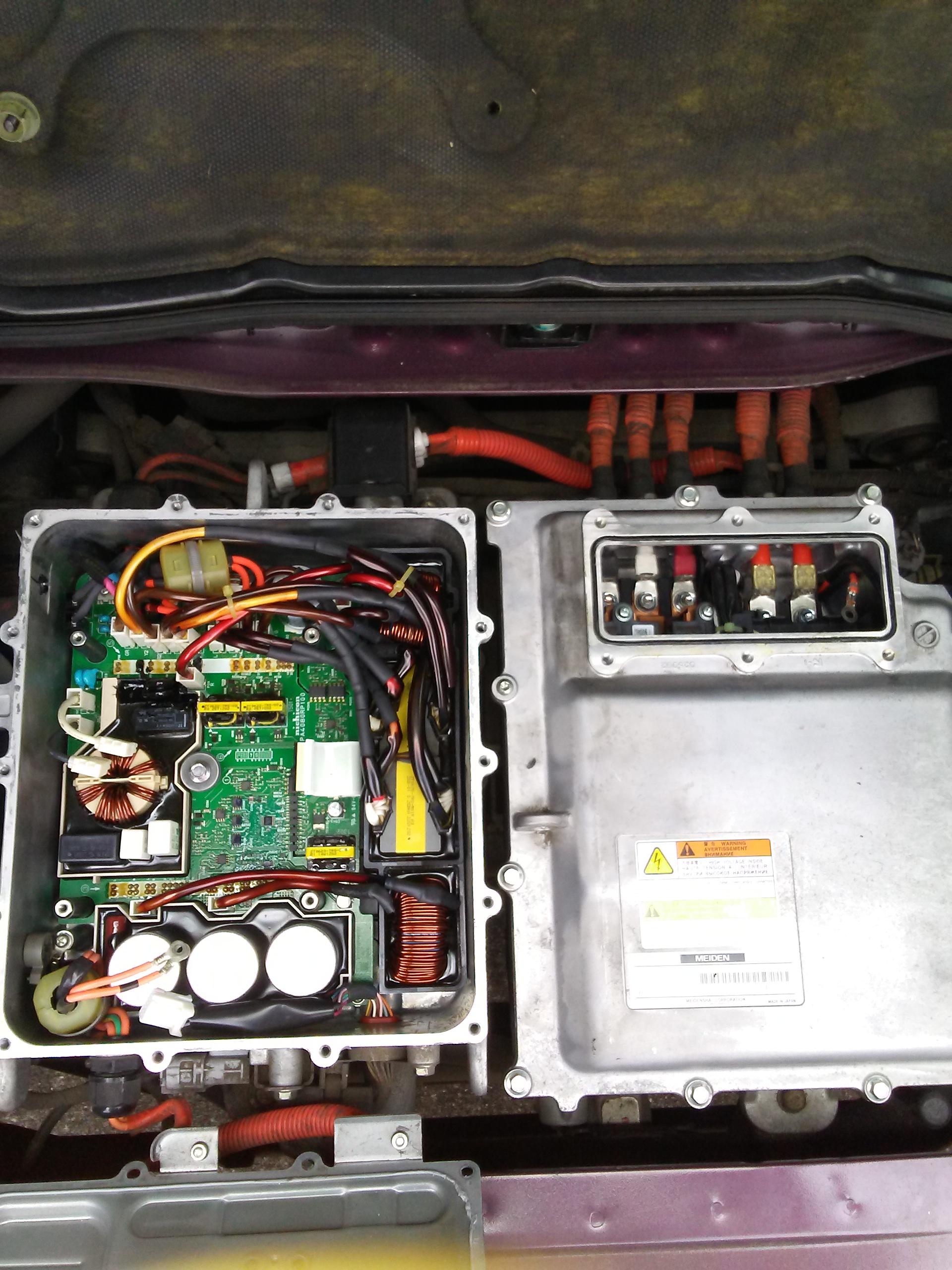
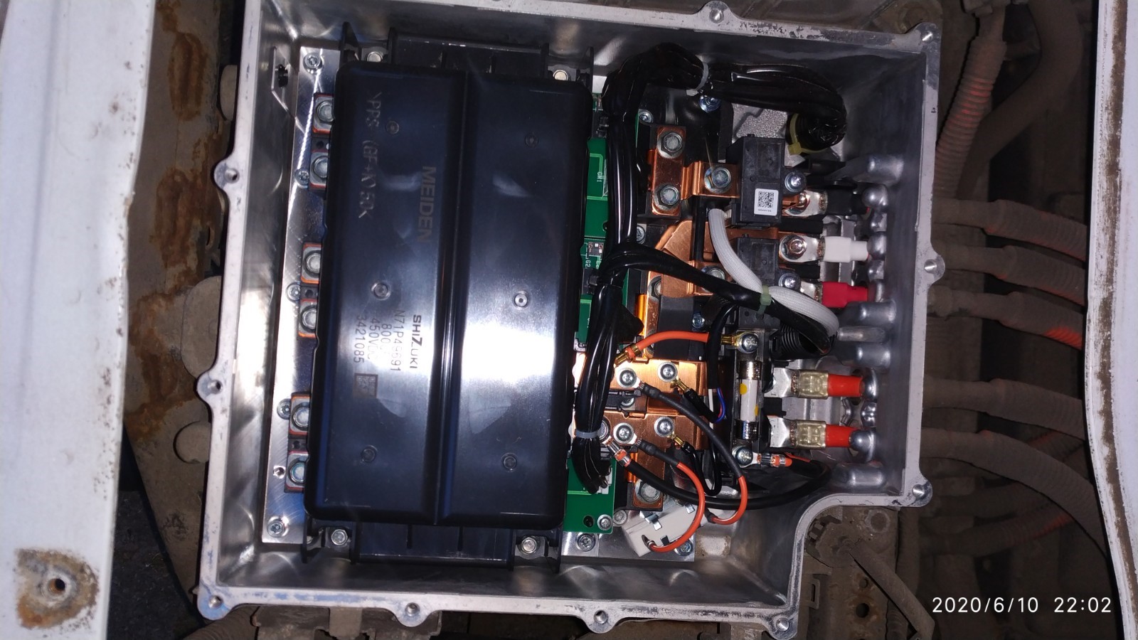
MCU with cover open
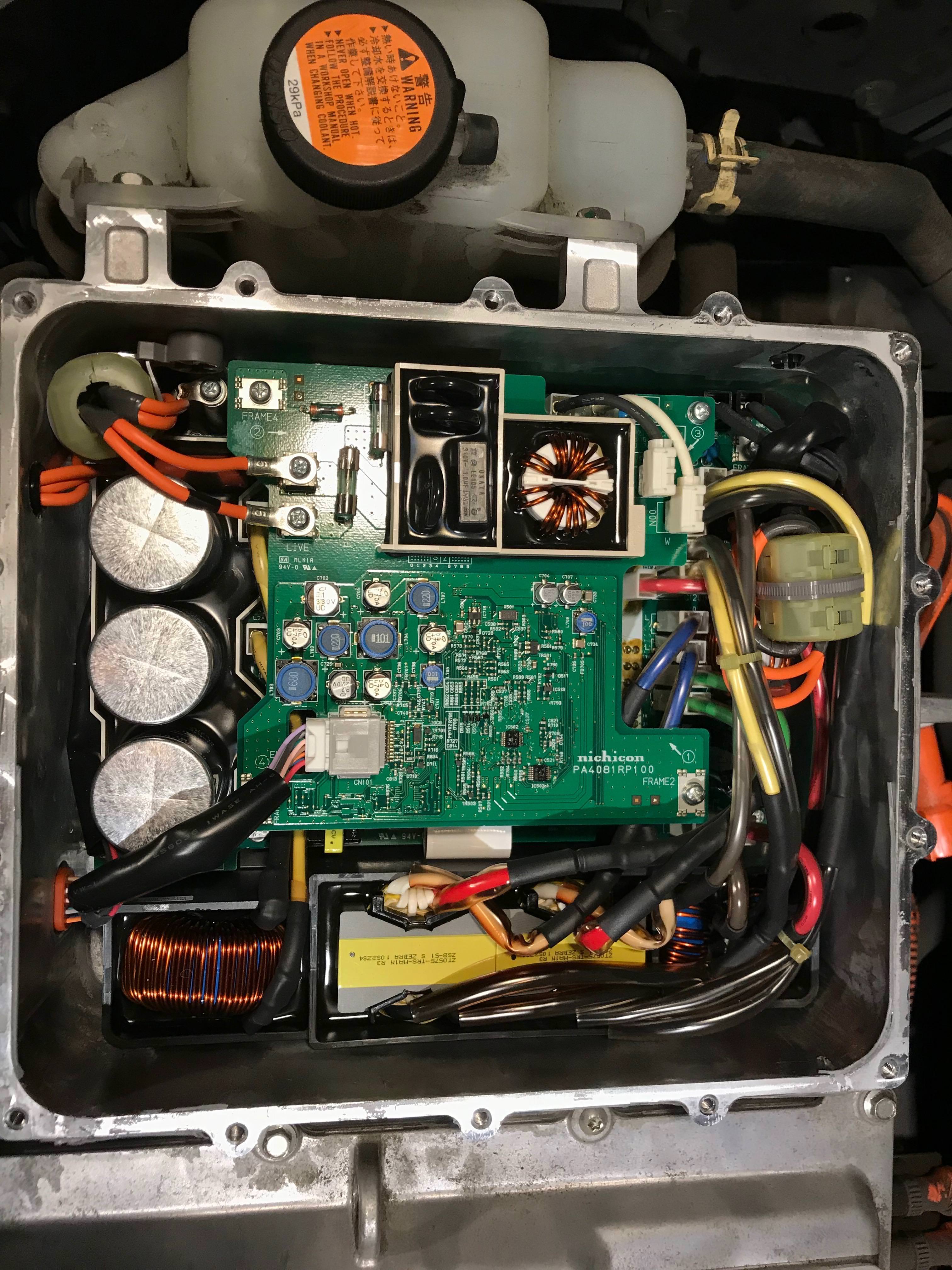
Here is an OBC picture with the cover open, note scorch marks on inside cover and the full exposure of the tops of the electrolytic capacitors (credit to coulomb for pointing out this indicator of high temperatures):
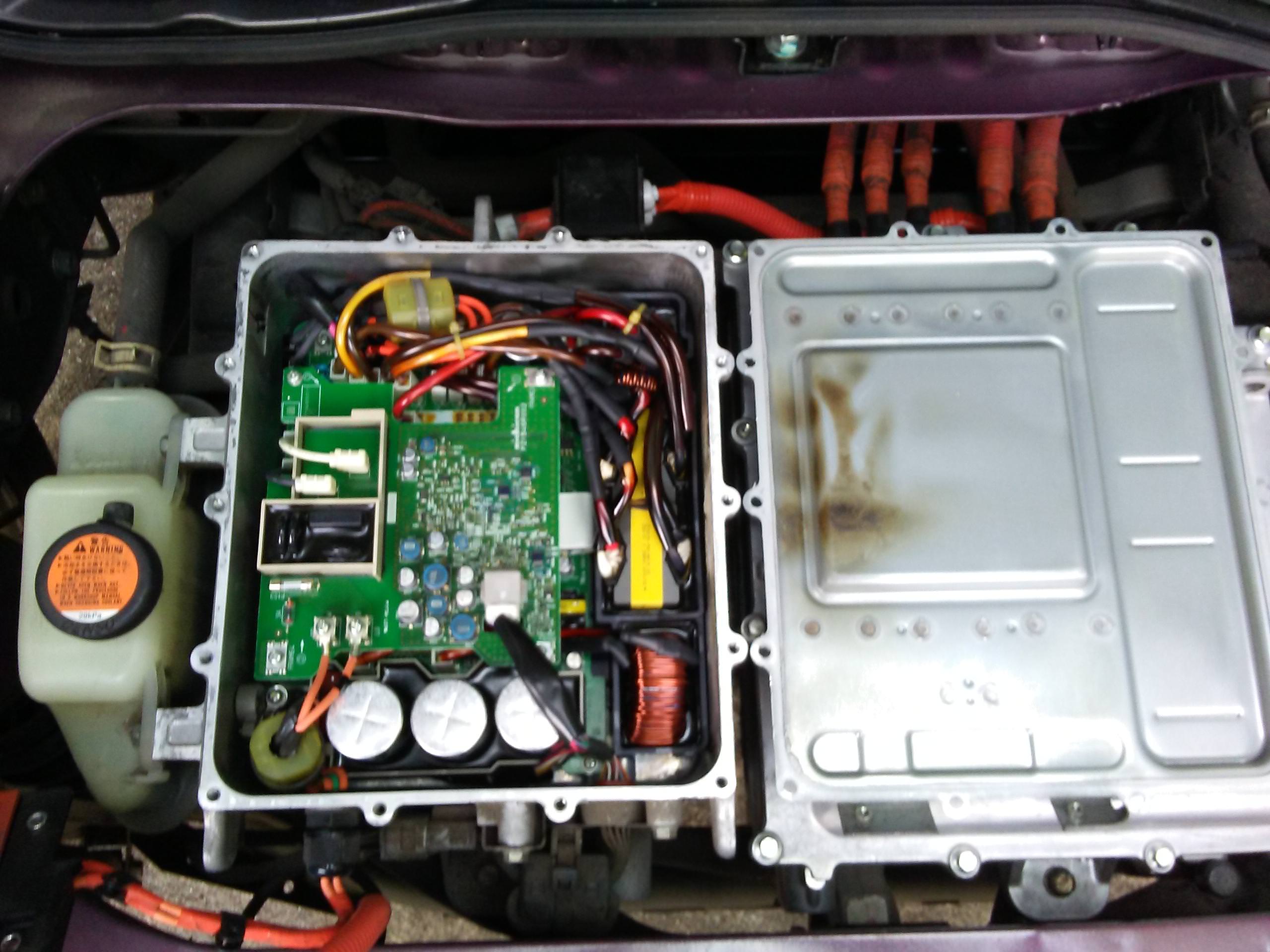
2015 version
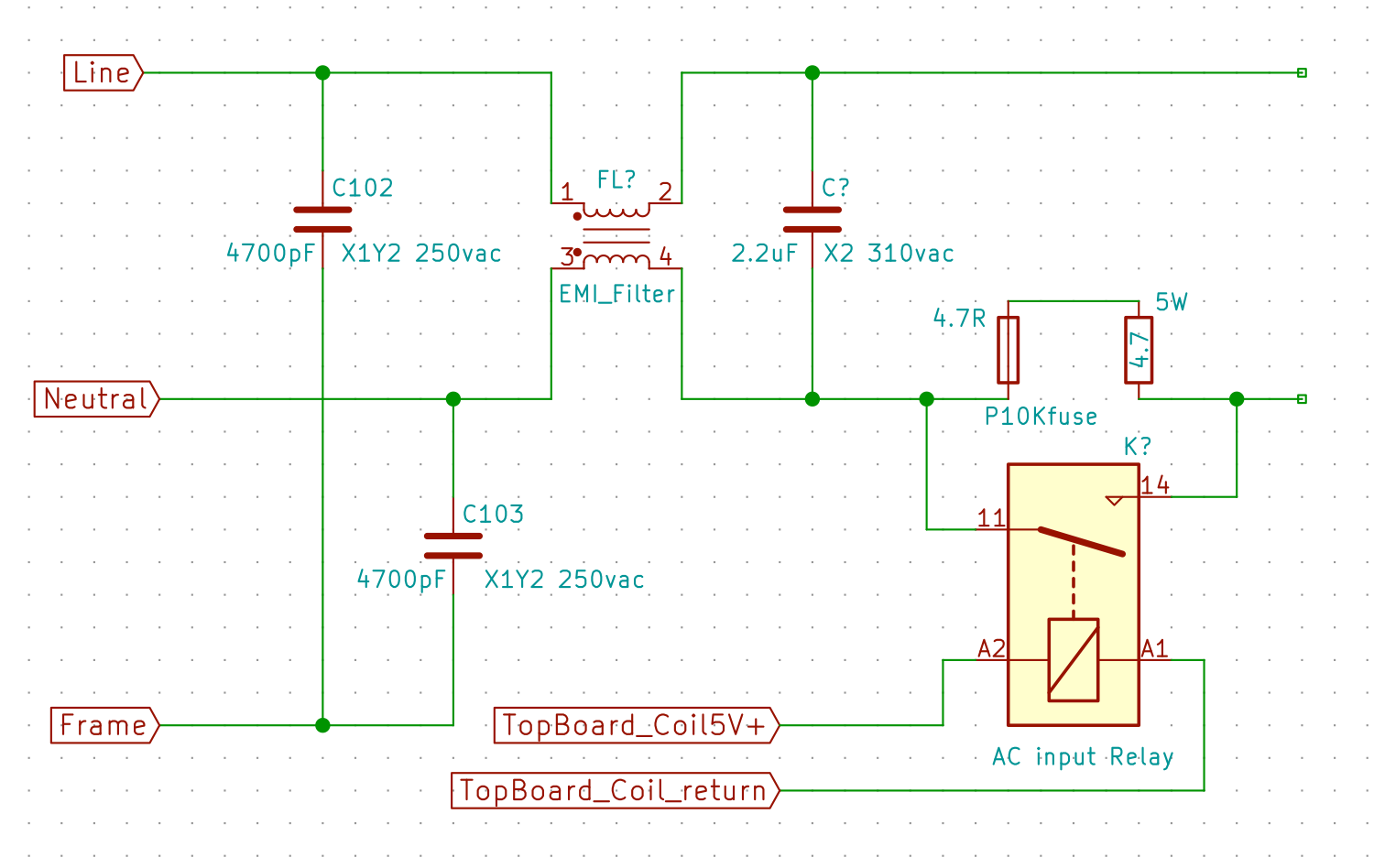
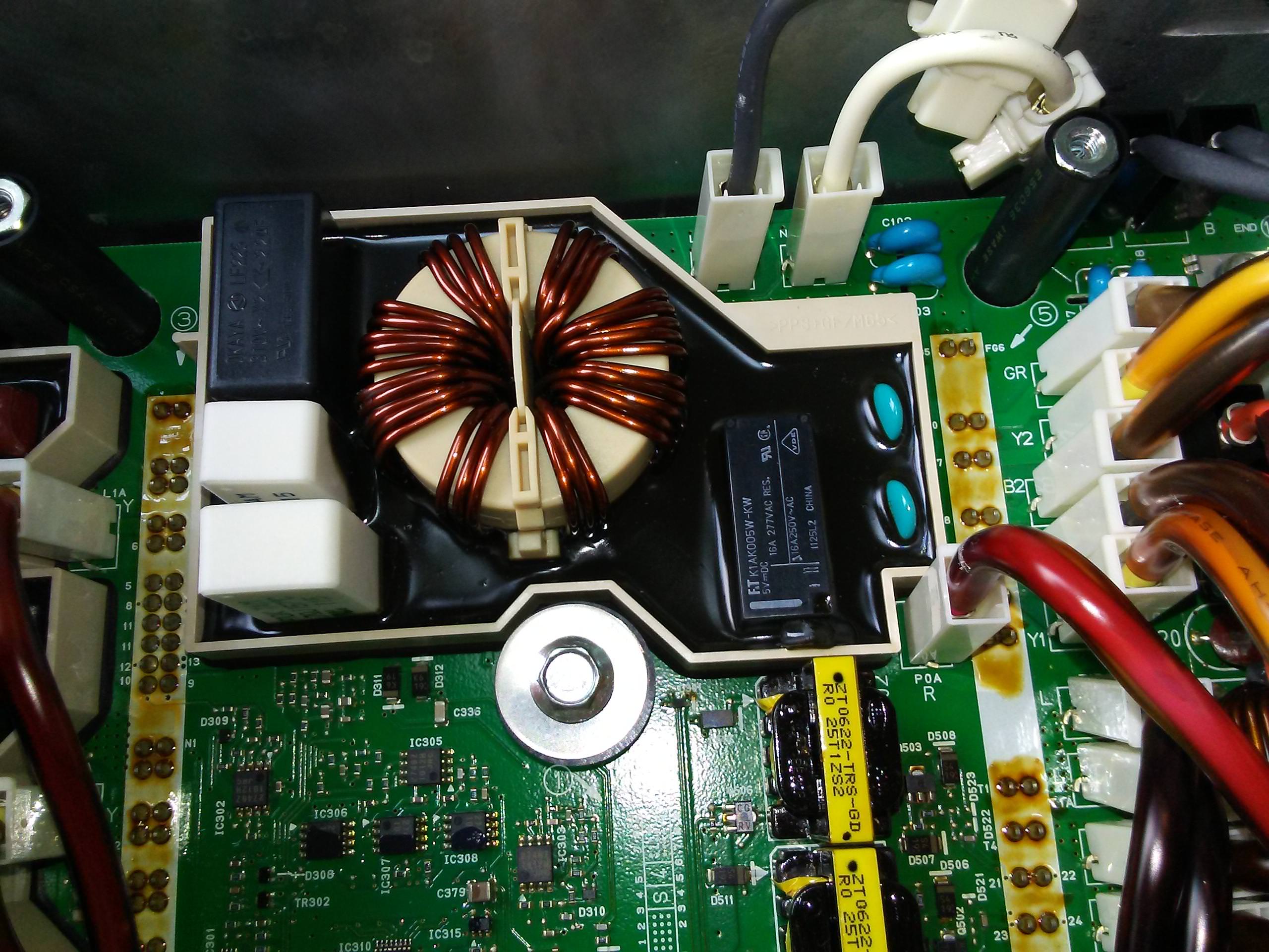
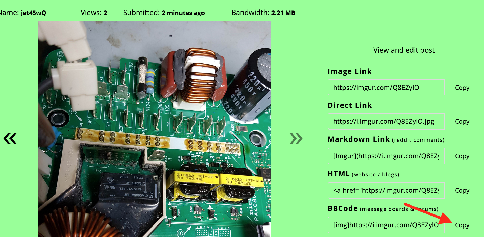
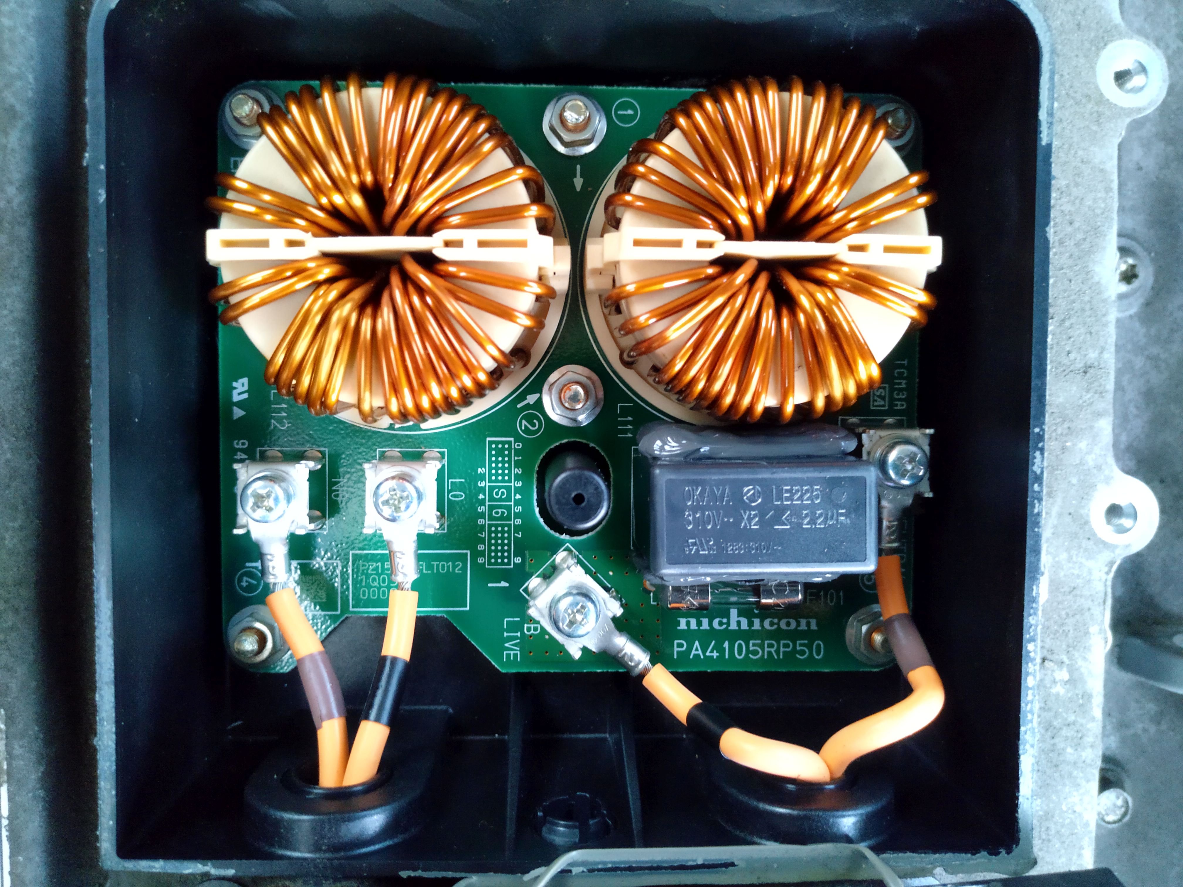
EMI Filter DogHouse (External Box on some versions)
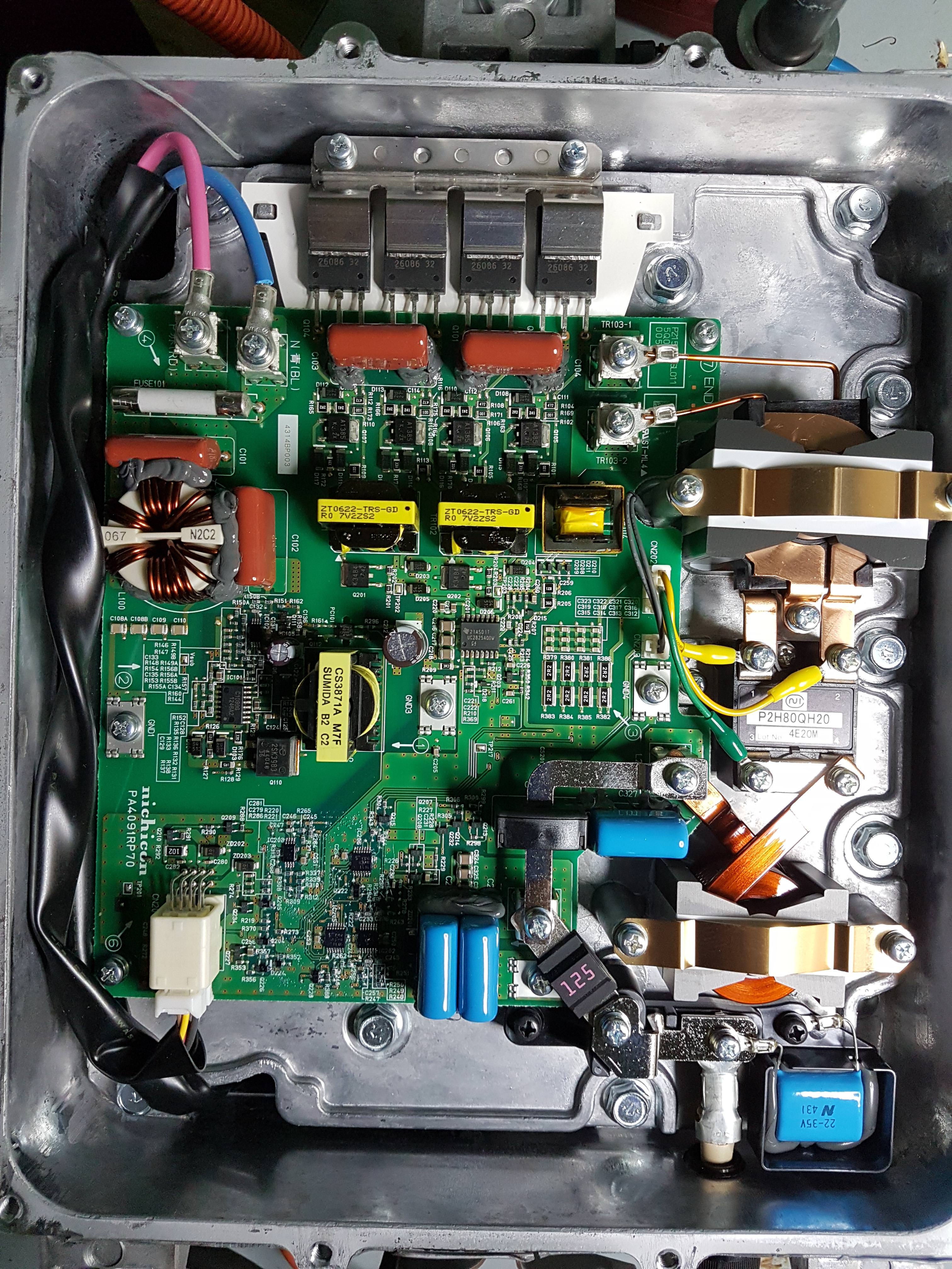
DCDC Converter Board in the bottom plenum from this post, http://myimiev.com/forum/viewtopic.php?f=23&t=4079&start=20#p36638
The INDEX Link
[Edit Jan 2024 The forum software was updated and the page numbering is now different, links may not be anchored correctly (tbd)
Also there is now a 10,000 character limit, so this post had to be broken into parts.
part 2 here: #1,264
part 3 here: #1,263
/edit]
This thread will be used to document the technical information and any schematics or firmware available to help troubleshoot and repair the OBC/DCDC Converter
Post #2 has troubleshooting steps and an index of this thread
Post #3 will hold a collection of circuit schematics
[edit Sydney EV video link showing a snubber capacitor repair with OBC removal]
Sydney EV video of iMiev charger repair
[Original post June 2018] There seems to be many failures reported lately (last 6 months or so)
Links to user's failures [and successful REPAIRS] in reverse order, latest at top:
[2023 edit]
##. Coulomb (July 2023). 2010 earlier version OBC in Australia. Failed isolation amplifier board in the Output Sense and Filter section beginning on page 110. Successful Repair by Coulomb
##. Philsuth (Aug 2021 }. Investigation of a 2010 earlier version OBC in Australia. Complete disassembly with some great details and pictures beginning on page 76. PhilSuth
[2020 edit to add additional repair efforts]
##. LucasH (Nov 2020). Does not chargge, but DCDC is working. LucasH
##. ZetaFunction (July 2020). Sebastian's issue with the switching power supply on the bottom board, a new issue never seen before starts here: ZetaFunction on pages 54-59 still in progress.
##. DutchLincoln (June 2020). Great pictures of disassembly to repair damaged snubbers.
http://myimiev.com/forum/viewtopic.php?f=23&t=4079&start=500#p41150
[previous list]
21. 11/28/2018, Reports and more repairs by Skylogger in WA
20. PM message, 10/2018, from tdigsi; looking for substitutes to replace the 680 and 220uF capacitors?
[EDIT: REPAIRED, replaced snubber caps and MCU fuse, now it is charging; going to replace HV caps anyway due to age and high mileage, est. >~5000 Hrs on caps.]
19. PM message, 9/2018, from Quixotix in Seattle; dealer says charrger is dead; recommended to request DTCs and open cover to inspect for damage, blown fuse, etc.
18. ChristopheFR, 9/2018, 2011 C-Zero in France, EVSE charging appears to start then quits, DCDC appears to work ok, Aux battery changed in 2015
17. skylogger#2, 9/2018, 2010 in Western Australia, blown snubber caps and MCU fuse, AC relay and precharge Rs
[EDIT: REPAIRED--SUCCESS!, 9/2018 ]
16. footswitch, 9/2018, 2012 not charging in Portugal, EVSE charging appears to start, then just quits, DCDC appears to work ok, still running with OEM Aux battery.
15. charliejuliet, 8/2018, failed charrger in Michigan UP, replaced with aftermarket DC/DC and Chademo charrger.
14. redcane, 8/2018, 2010 not fully charging in Australia (east coast), OBC was replaced with a 2015 unit under recall in January 2017.
[EDIT: 1/8/2019,REPAIRED, replaced snubber caps and MCU fuse. Also replaced the pre-charge resistor, but that was not due to the OBC failure.]
13. skylogger, not charging in Western Australia, found blown surface mount capacitors.
[EDIT: SOLVED AND REPAIRED,8/12/2018, see picture of a twisted resistor causing open circuit on voltage monitoring]
12. beeline, 6/18, 2012 not charging, dealer estimates $4800+tax
11. mikedufty, 3/18, 2010 Australian model not charging fully in WA, charrger was replaced under recall. Dealer now pointing at EV-ECU as bad.
10. 1pk, intermittent charging level 1 and 2, found cracked bypass resistors at AC relay
[SWAPPED OUT OBC WITH USED 2013 UNIT, 8/13/2018]
9. Lic, 4/18, getting condenser timeout error P1A15, no main(+) contactor indication
8. jray3, 6/18, Mr. Bean dc converter not working, blown 20A fuse in the inverter
7. luvmymiev, 6/18, Category: i'll take bad charrgers for $4000--The question is:What did the dealer find?
6. electronpusher, 6/18, car not charging in New South Wales, blown snubber capacitors in the potted doghouse and fuse in the MCU.
[EDIT 10/7/2018: REPAIRED , replaced snubber caps and fuse and now it's working again, Good Job!]
5. Antaris, 3/18, service manager says the on board charging unit has failed.
[EDIT: REPLACED, Mits Canada replaced it for $800 Cdn]
4. fresnomiev, 3/16, dealer replaced charrger while troubleshooting by parts swapping, issue was MCU inverter.
3. pluto, 2/18, code 39 OBC, abnormal PFC voltage,
2. Sbess, 10/17,dealer says bad charrger
1. TorranceMiEV, not charging
iDriver, Nov 28, 2017, charrger fuse in MCU blown
Just for the historical record, mccluer had a very early report of charrger failure back in 2012
also DonDakin in 2013
also Malm, 3/2016
===
[edit: add a section of pictures of various items frequently referenced]
This shows the OBC on the left with the cover off and the upper control board removed showing the power board and flat ribbon cable, and the MCU on the right with the access cover open:
MCU with cover open
Here is an OBC picture with the cover open, note scorch marks on inside cover and the full exposure of the tops of the electrolytic capacitors (credit to coulomb for pointing out this indicator of high temperatures):
2015 version
EMI Filter DogHouse (External Box on some versions)
DCDC Converter Board in the bottom plenum from this post, http://myimiev.com/forum/viewtopic.php?f=23&t=4079&start=20#p36638
Last edited: