MCU 20A 450VDC fuse investigation

Mitsubishi i-MiEV Forum

Help Support Mitsubishi i-MiEV Forum:

This site may earn a commission from merchant affiliate links, including eBay, Amazon, and others.

kiev

Well-known member
Joined
May 3, 2015
Messages
2,214
Location
The Heart o' Dixie
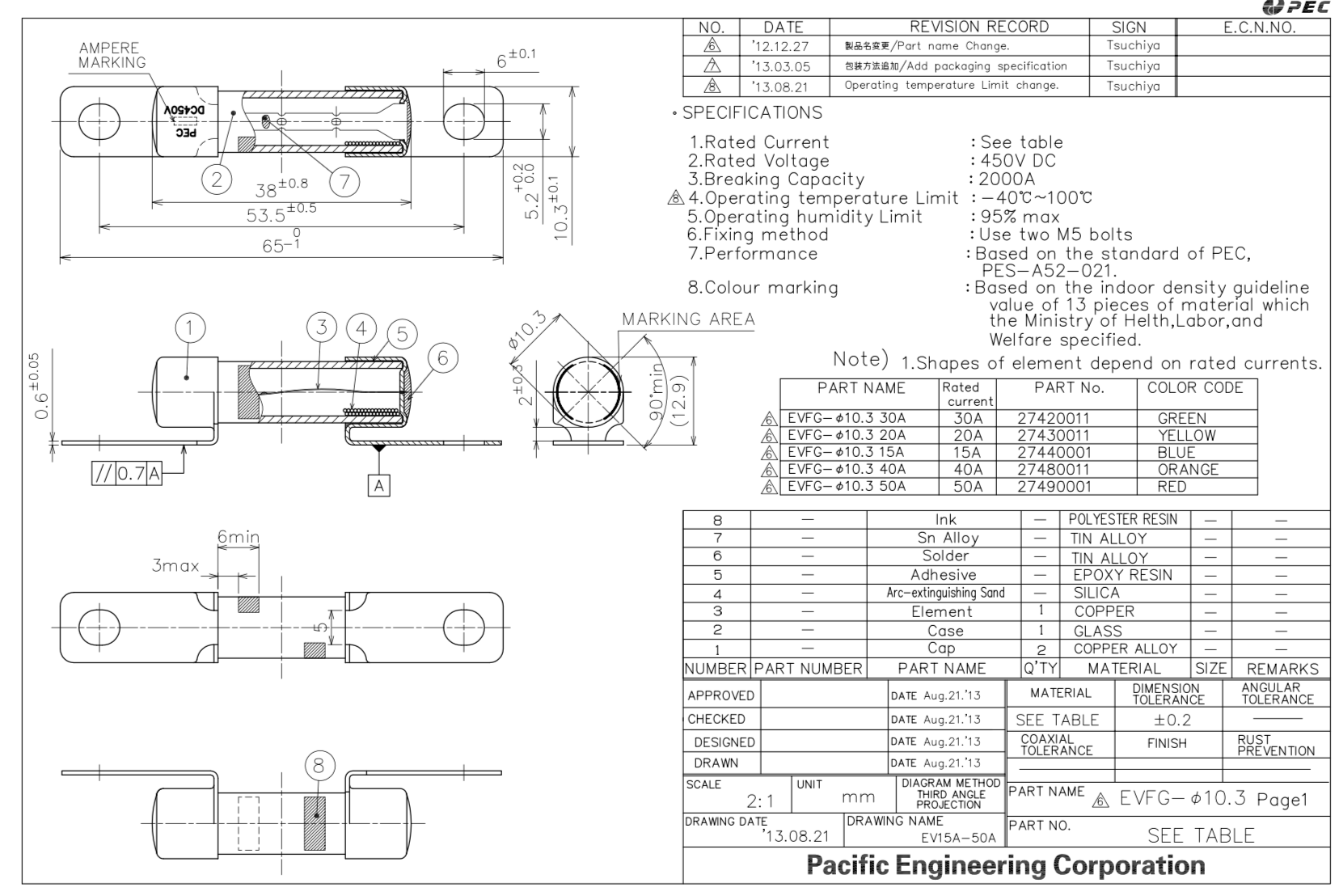
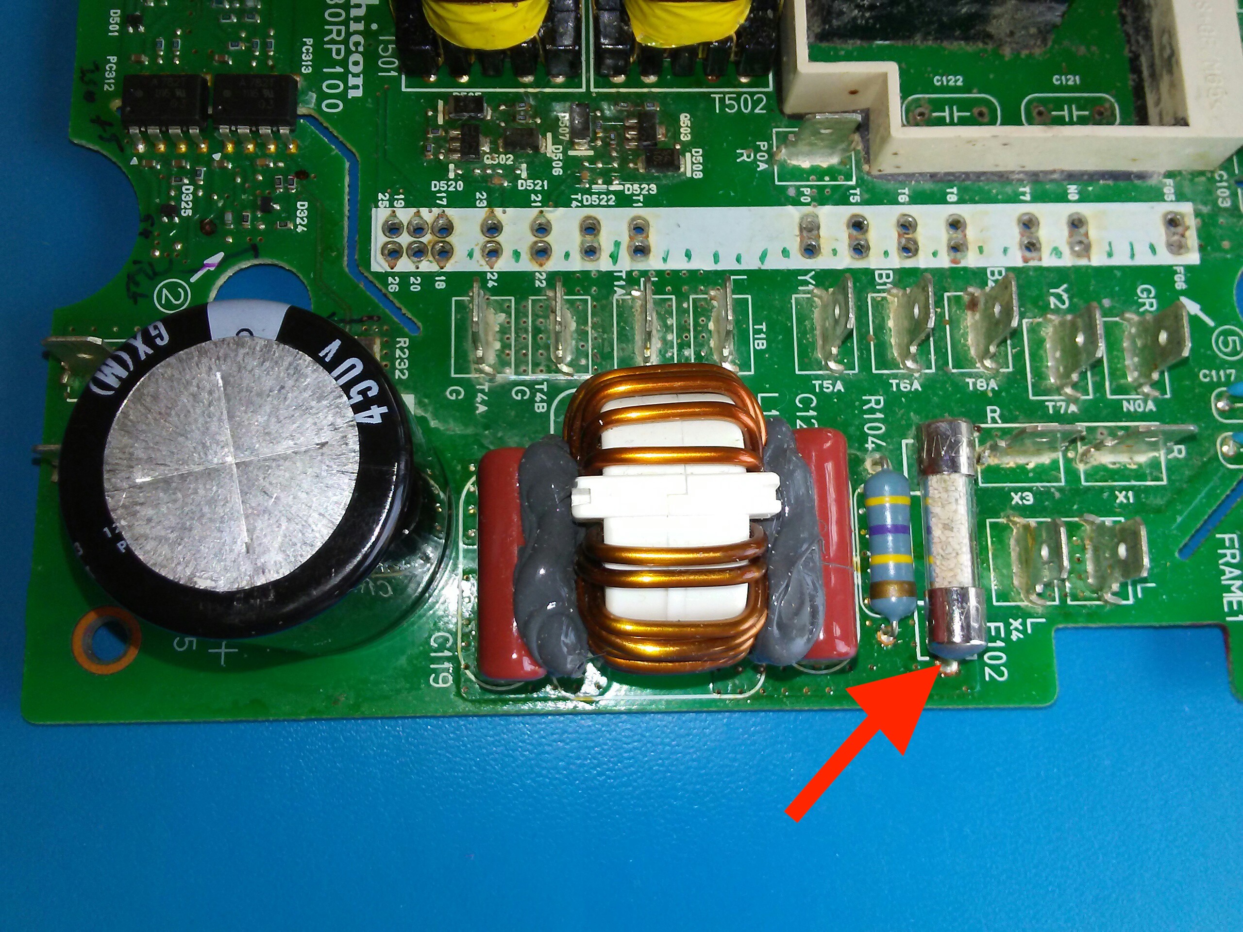
If for some reason the Motor Control Unit fuse blows, then the On-Board Chargger (OBC) and DCDC converter (High Voltage-to-12VDC) will no longer function, since they have lost their connection to the Battery Pack.

If the fuse blows during operation of the OBC, then it is very likely that the two snubber capacitors in the HV output section will also be destroyed. This scenario has been reported dozens of times in the past 2 years in the OBC Troubleshooting and Repair thread.

So looking at this another way-- could the fuse have a limited lifetime due to age, wear and tear, etc?

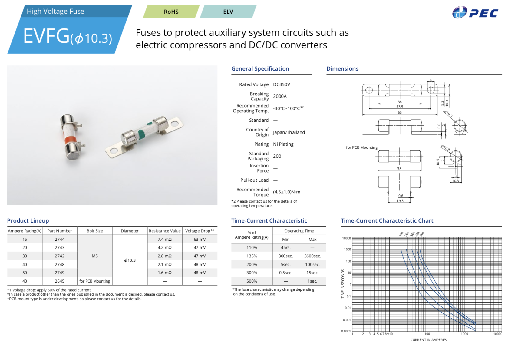
Environmental lifetime factors for fuses are not listed in the datasheets, but i would suggest that automotive electronics has a significant vibration factor for which stationary applications are not usually exposed.

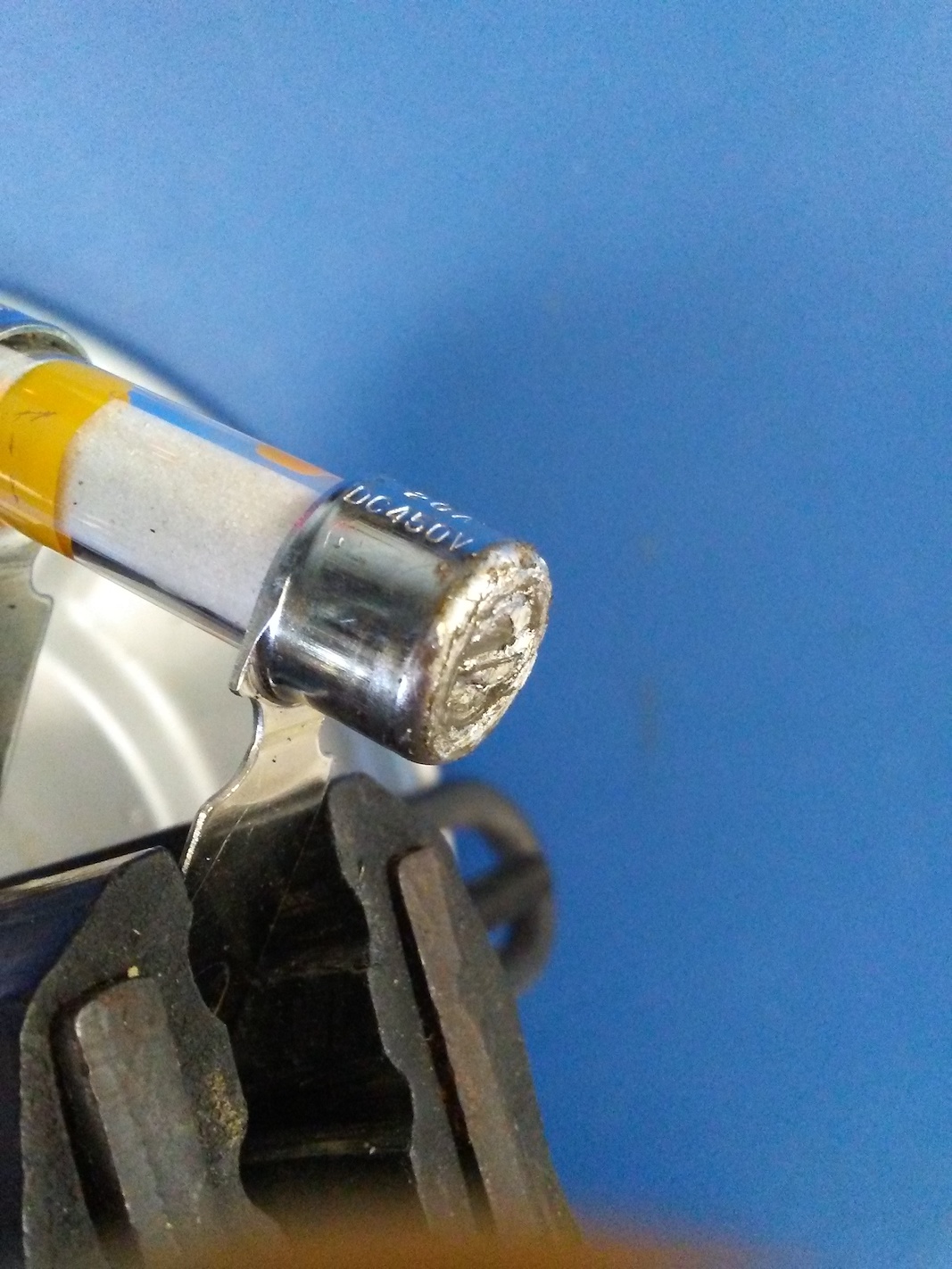
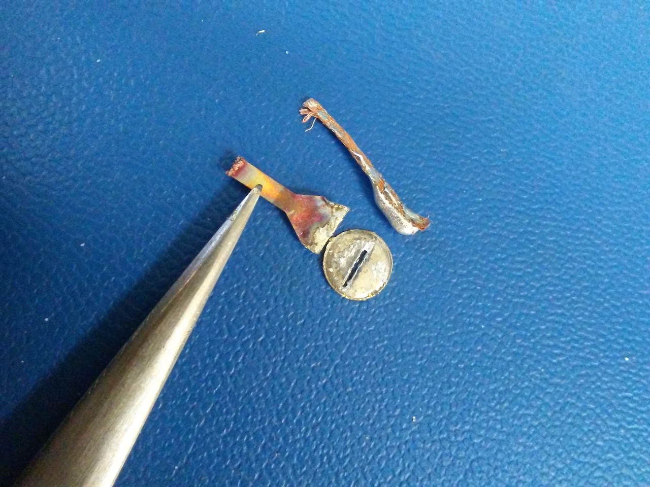
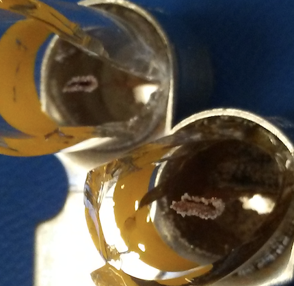
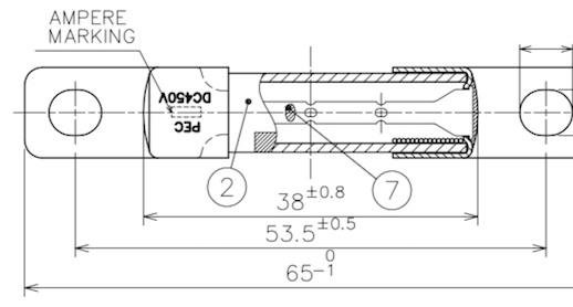
What if the combination of repeated thermal cycling during normal OBC and DCDC operation, plus the mechanical shock and vibration from normal driving on our typically smooth and pothole-free highways over several years, has caused the fuse filament element to develop metal fatigue cracks leading to breakdown?

Could this be the root cause of the numerous OBC failures?

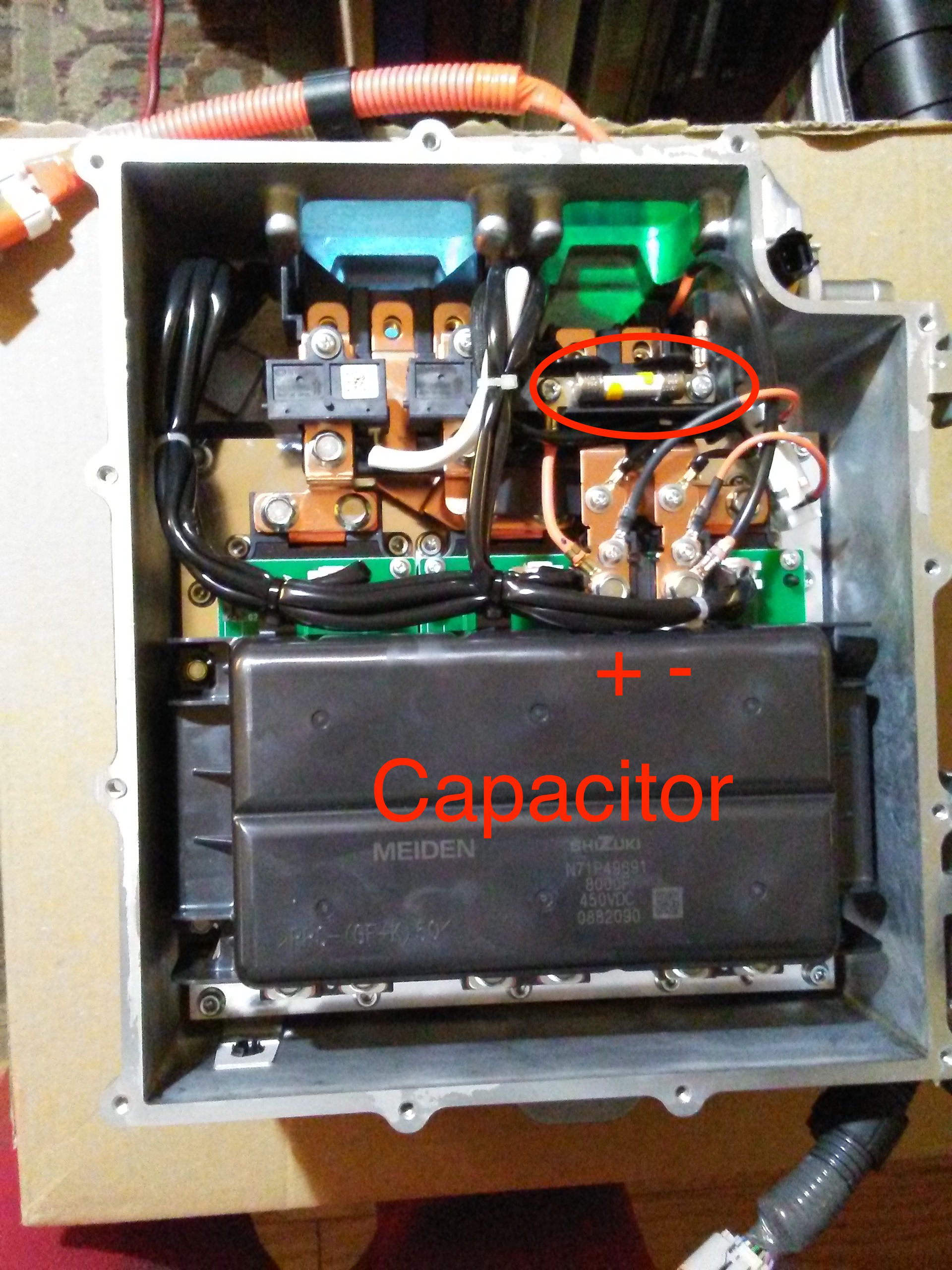
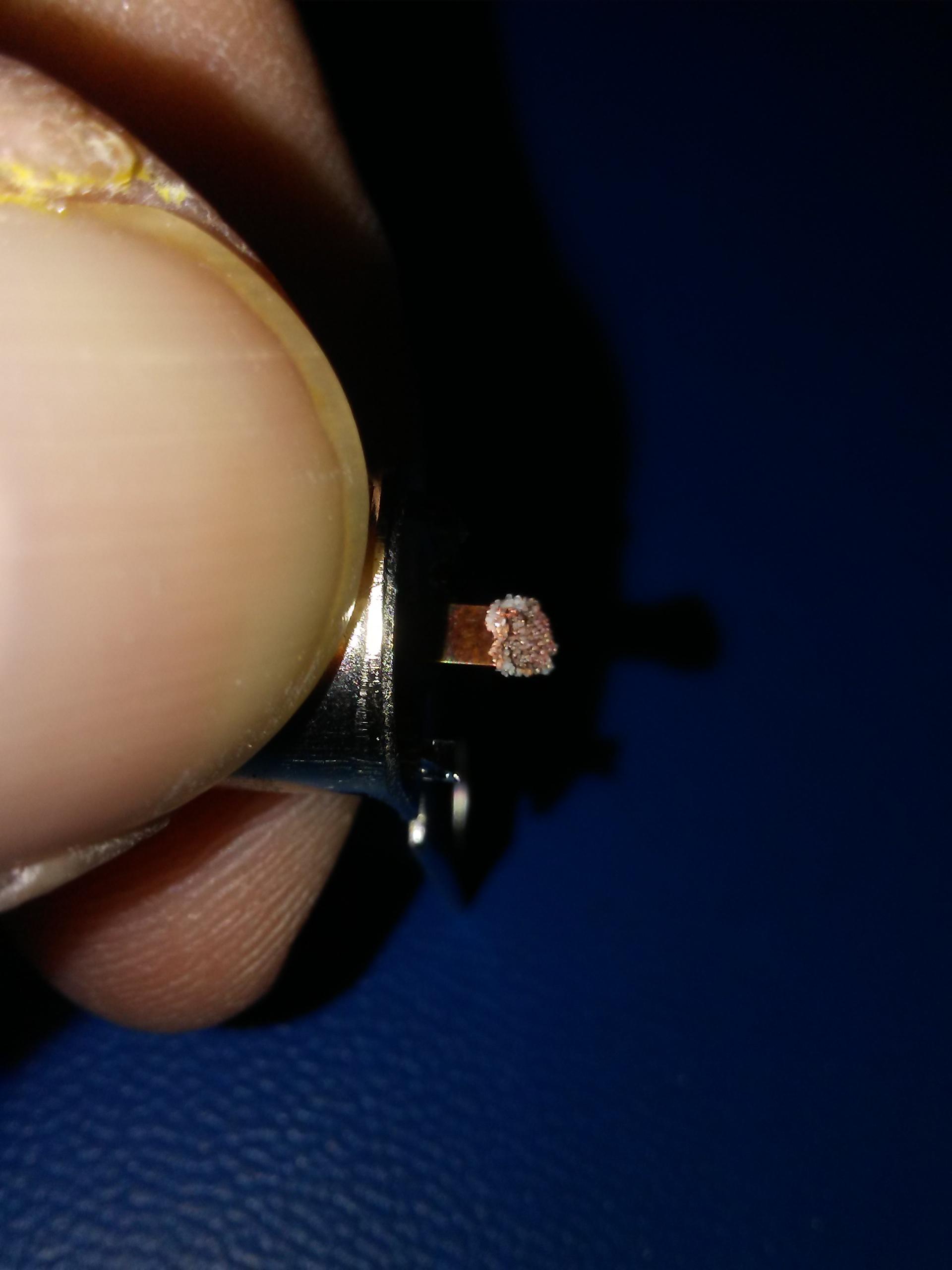
edit: add photo of open MCU to show the fuse. It is behind the small access cover, so no need to remove the cover to replace it.

tEh7pHq.jpg
 
some photos of the fuse construction and of a failed fuse:

overview
KxeNPcp.jpg


found ring of cracked solder on the endcaps--evidence of vibration
ImOlDOx.jpg


filament is inserted thru a slot and soldered to each end cap
EaodJRn.jpg


slot and solder blob removed
lyn1UQj.jpg


when the copper filament melts, it glassifies the sand and forms a hollow sand tube
KMHwl4v.png


molten copper globules fused with the sand tube
fxKFRjl.jpg
 
This is the datasheet for the 10.3mm diameter fuse from Pacific Engineering Corporation, PEC:

DYqeyPs.png


and the drawing showing the construction details:

DloTbKw.png
 
i measured the thickness of the copper filament at 0.101mm, and the width at 1.97mm. This cross sectional area comes to that of about a number 24 AWG copper wire, which has a fusing current of about 29 Amps. This can be seen on the datasheet for the 20A rated fuse.

But on the fuse drawing it shows that the filament is actually a perforated copper strip and not completely solid--there are punched out sections to thin the filament. So the resistance is given as 4.2mOhms, when i calculated it would be ~2mOhms for a solid strip.

XyoNP91.png


i saw evidence of the perforations when i first dismantled the fuse--there were 2 parallel sand tubes at one of the break joints. But it fell apart before i could get a photo.

The soldered filament into the end caps can be viewed as a fixed-fixed beam clamped at both ends for mechanical vibration analysis.

xxbnPgy.png


This leads me to believe even more that vibration can result in fatigue cracks in the filament, especially in the thinned out sections.

So i think that the fuse mechanical lifetime in our cars is about 5-6 years or so, although a couple of folks reported really early failures which could be infant mortality, a manufacturing tolerance factor.

Maybe this should be a maintenance item--just replace it after 3 years to be safe.

i'm gonna buy some 40 Amp replacement fuses. If someone wants to swap out their fuse before it breaks, i would like to dissect a used older fuse to see if there are any fatigue cracks beginning to grow.
 
Very interesting

Construction wise, that looks very much like a standard household fuse from the 1930's or '40's - I guess I would have expected something just a bit 'higher tech' from a 21st century electric car

Also seems a bit odd that the circuitry is designed so something else fails when (or because) the fuse fails - Kinda defeats the purpose of fusing a circuit, doesn't it?

Don
 
Another clue that the MCU fuse is suspect of mechanical failure, is that the little HV output fuse in the OBC has never been reported to have failed, nor has the same fuse in the HV input section of the DCDC converter.

Here is the final HV output filter stage of the OBC showing the HV output fuse, it's 20A but in a much smaller package. The schematic is in the OBC troubleshooting thread.

3Qnp7ma.jpg
 
kiev, thanks for presenting this and further pursuing it. Like your detailed photos! High Voltage dc fuses are interesting from the standpoint of needing to be self-extinguishing, and hence the sand-surround. An intriguing thought: wouldn't the sand act as a vibration dampener? I always assumed the sand was packed in there, but I can't tell from their drawing.

Ever since you first identified this possibility, I've been meaning to look back at the circuitry to correlate the OBC/dc-dc component failures with suddenly seeing this HV circuit open up while it's running. This fuse has an interesting position, as it blowing out affects the output of the OBC and the input to the dc-dc - and you just pointed out that the fuses for each of those circuits have not blown!

Going to 40A is certainly a quick way of getting a physically-beefier fuse element in there.

I haven't done any literature searches to see if there is perhaps a MIL-SPEC equivalent, since such fuses usually have stringent vibrations requirements. I don't even know how to look nowadays...

Anyway, I'm game to replace the fuse in my two i-MiEVs with a 40A critter and be happy to chip in to buy a few and let you dissect my old one - send me a PM.
 
Hi Kiev and Joe,

Are you comfortable replacing a 20A fuse with a 40A?
Would the 30A be a better choice?

If the mounting legs are vibrating and breaking, what about building up a 'mountain' of silicone around each leg?
This might also help lengthen the life of the fusible link.

Thanks and good health, Weogo
 
Excellent work KiEV, thank you! The rigid mounting of this fuse could be another factor, with thermal cycling moving the end caps back and forth at a different rate than the element. As in my EV conversions, I used a Littelfuse KLK20 as a temporary replacement, and when mounted in spring clips, it naturally will experience less mechanical stress on the mounting points. I found similar fuses also available with wire crimp terminals on the end caps, which could allow a very low strain mounting of the fuse.
https://m.littelfuse.com/~/media/el...nd-ul-fuses/littelfuse_fuse_klk_datasheet.pdf
 
jray3 said:
when mounted in spring clips, it naturally will experience less mechanical stress on the mounting points.
I can almost imagine the metal fingers in the original fuse creating a "tuning fork" of sorts. Add impulses from normal car vibrations and jolts, and the fuse could be doing a merry dance, fatiguing the delicate fusible parts. A set of shorter, fatter, and stiffer clips might be enough to dampen the vibrations and keep the fuse alive longer.

Recall that the fuse blowing first is one of our several theories as to how the on-board charrgers are blowing up.

"The fuse protects the cable", so the fuse should ideally be suited to the cable. I agree that if we are forced to go to a higher current, 30 A or 25 A if available would be preferred over 40 A.

[ "fusible". ]
 
Okay, this is enough evidence of mechanical failure for me to put a pre-emptive fuse replacement on the maintenance schedule. My original lasted 80k miles, but a friend's only made it 45k. What lower mileages have the OBC fuses blown at? I'm thinking of a 40k interval (so am already halfway there on my 1 year-old fuse). If someone researches a replacement (especially with a spring clip mount), please post it.
 
kiev said:
If the fuse blows during operation of the OBC, then it is very likely that the two snubber capacitors in the HV output section will also be destroyed. This scenario has been reported dozens of times in the past 2 years in the OBC Troubleshooting and Repair thread.

So looking at this another way-- could the fuse have a limited lifetime due to age, wear and tear, etc?
This theory makes a lot of sense. By my calculations, the fuse has approximately 9 amps flowing through it for up to 5 hours at a time during a level 2 charge. While it may not warm to any significant degree, it is a heat load that can fatigue the fuse. Also, the car is usually driven after being charged, so now a warm fuse is getting jostled by driving. Plus, as the fuse ages and develops weak spots, this causes more heat buildup, further degrading the fuse until it eventually breaks, usually under the thermal strain of charging. The DC-DC converter can pull 3 amps at most, usually less than an amp during normal operation, so even a fuse on the verge of blowing could keep power flowing without too much trouble while driving, which means we see most failures during a charge.

When this fuse goes, the full charging current is interrupted, which could likely be causing a voltage spike on the charger side and blowing the capacitors by over-voltage.

kiev said:
...driving on our typically smooth and pothole-free highways...
So jealous :lol:
(https://scontent.fakc1-1.fna.fbcdn.net/v/t1.0-9/52924233_2591674024207673_6556911349991997440_n.jpg?_nc_cat=104&_nc_ht=scontent.fakc1-1.fna&oh=6765814b27afa9352670add423e977c7&oe=5D8F852F)
 
jray3 said:
Okay, this is enough evidence of mechanical failure for me to put a pre-emptive fuse replacement on the maintenance schedule. My original lasted 80k miles, but a friend's only made it 45k.,

Do you have information on how both cars were charged most of the time L1 or L2. Any significant charging habit difference between them. If it is this fuse causing a cascade failure (likely). It seems like higher amperage would stress it more, if it is heat stress that is the main culprit.

Aerowhatt
 
jray3 said:
If someone researches a replacement (especially with a spring clip mount), please post it.
The fuses look very much like standard 1.5 inch household cartridge fuses . I have a pair of 20 amp AC fuses mounted in ceramic snap in holders that I'm using in the circuit for charging my Volt - They are connected to a pigtail which plugs into the 40 amp circuit for my wife's seldom used ceramic kiln

Anyway, it doesn't seem like it would be very hard to buy a fuse holder, remove the snap in holder pieces from each end and solder those pieces to the 'legs' you cut off your old fuse - Then you'd have a snap in fuse which could move a tiny bit as it heated and cooled and that would take the physical stress off the internal components of the fuse . . . . might make it less prone to failure

How hard is it to change that fuse? Pop the top off the OBC and it's right there, easy to get at, or do you need to remove the charger from the car?

Don
 
It's in the MCU under the small access cover plate. (hence the thread title...haha)

It is very easy to access, and i may just make a temporary jumper with a piece of 26 or 24 AWG.

Added a picture of an open MCU to show the fuse in the first post.
 
@kiev, were you able to find a source (other than Mitsu) for that MCU fuse? In looking at your datasheet, it looks like the PEC part number is 27430011. I've had no luck with my searches and I like jray3's suggestion of a Littelfuse KLK020, except I'm unclear as to how to hold it in place for the screw-mounting tabs (are mounting clips available?). Perhaps time for me to get proactive and do some preventive maintenance on my two i-MiEVs.

Coincidentally, one of my Xantrex 3.3kW grid-tie inverters died this week after working flawlessly for 13 years. It had a blown Littelfuse KLK020 - replacing it revived the display circuitry but the inverter is still dead... yet another project (sigh).
 
i found these at Mouser, 0HEV030.ZXISO. The ISO format is the one used in the MCU and it is 10.3mm diameter, not 7.2mm. (PEC103 vs PEC72)

The 20A and 40A were out of stock with 12 week delivery and min order of 240 pieces, so i bought the in-stock 30A. My thoughts were that any short circuit of the wires between the OBC and MCU that will take out a 20A fuse, will also take out a 30 or even a 40.

i haven't found the drawing to show the dimensions and specs of the fusible element yet for comparison with the PEC fuse. i wanted to buy some of each rating for testing but the min order is outside of my budget.

https://www.littelfuse.com/~/media/...es/littelfuse_lowcurrenthevfuse_datasheet.pdf
 
Interesting thread, however to play devils advocate for a moment, I am quite sceptical that the fuse could be the initial point of failure.

It seems much more likely that the dielectric of the capacitor is breaking down, either due to the capacitors being marginally speced, degrading with age, or a slightly out of the ordinary voltage spike, and that the short circuit current of the failed capacitors would be enough to blow the fuse.

Convince me otherwise. :)

Another thing that makes me sceptical is that I can't believe the designers wouldn't have performed live tests with a deliberately under rated fuse to observe the behaviour of the unit when the fuse blows, especially if there is anything that could cause a voltage spike when the fuse blew.

Of the reported failures how many are capacitors only, how many are fuse only, and how many are capacitors and fuse ?
 
Both of the charger replacements I’ve done had both failed capacitors and fuse. The 40k failure had been charged primarily at L1, and the 80 kilomile failure was almost exclusively charged on L2 and CHAdeMO. Both cars did have L1 charging interrupted by yanking the power plug a few times.
 
From memory these two capacitors are in parallel ? If so, another good question would be in all cases where the capacitors have failed have both of them failed together or have there been any cases where only one failed ?
 
Back
Top